Realistic Tamiya Lights
The popular Tamiya hop-up light kit is a tempting choice for adding lights to 1/10 RC car models. However, like many other light kits available, a naive wiring of the kit will result in some lights not behaving like their counterparts do in a real car. In this blog post we explain how to achieve a more realistic behavior using a programmable remote control. We will illustrate the approach using a Radiomaster MT12 control running EdgeTX.
Problem
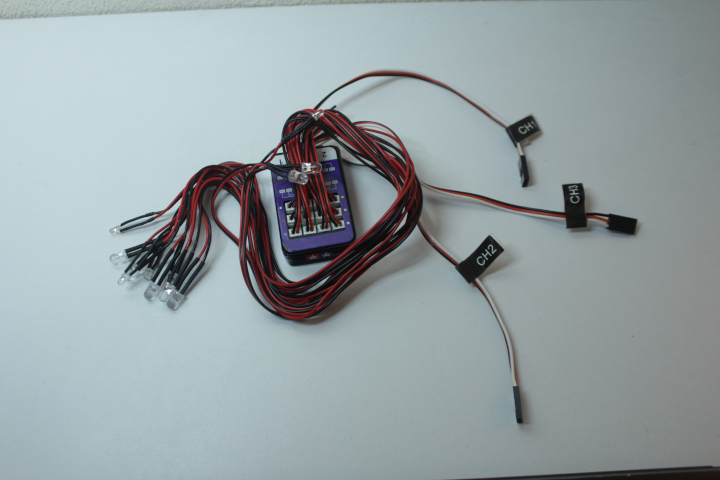
The light kit comes with 12 leds as follows.
- 4 yellow leds
- 2 red leds
- 4 white leds
- 2 blue leds
The kit comes with 3 pairs of Dupont connectors labelled “CH1”, “CH2”, and “CH3”. Each pair consists of a male and a female connector so that one connector plugs into the corresponding channel of a given receiver and the other connector plugs into the corresponding component of the RC car. The usual component for channel 1 is the steering servo and for channel 2 is the ESC (Electronic Speed Controller) that controls the motor. There is no usual component for channel 3. The following picture shows the kit connected into a receiver naively by following the labels, i.e. CH1 into channel 1, and so on.

When we connect the light kit naively, the lights work in the following way. The pair of blue leds is always on. A pair of white leds turns on when channel 3 is high. Pushing the throttle forwards with channel 2 turns on the other pair of white leds and pushing reverse with channel 2 turns on the pair of red leds. Steering left with channel 1 turns one pair of yellow leds and steering right turns on the other pair.
Given the way the lights work when we connect the kit naively, we do the following to achieve a more realistic behavior.
- Remove the blue leds. This is a matter of preference and our preference is to not have any leds always on because we feel it makes our RC cars feel more like toys than scale models.
-
Keep the yellow leds the way they are.
-
Have headlights and tail lights turn on when channel 3 is high.
For this reason we connect an additional pair of red leds in parallel
with the white leds that turn on when channel 3 is high.
-
Turn on brake lights when we brake and reverse lights when we
reverse. This is the challenging part of realistic lights with this
kit. Consider the following video that shows the behavior of the
white and red leds corresponding to channel 2 given throttle actions.
Our solution
To solve the problem of turning brake and reverse lights realistically, we keep the leds that are already controlled by channel 2 the way they are and we track the state of the brake and reverse actions of our RC car with a programmable transmitter (remote control).
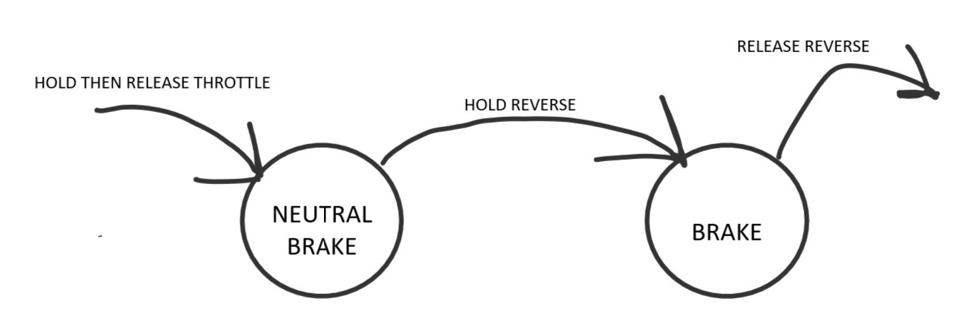
We track the state of the brake action with the following rule: a hobby-grade RC car brakes when we hold the throttle in reverse right after we hold the throttle (forward). The following diagram illustrates this brake rule. Given a transmitter and an RC car, you can track the brake action by following the diagram with your finger as you interact with the transmitter. Your finger should enter the diagram from the left following the arrow “HOLD THEN RELEASE THROTTLE” and should leave the diagram from the right following the arrow “RELEASE REVERSE”.
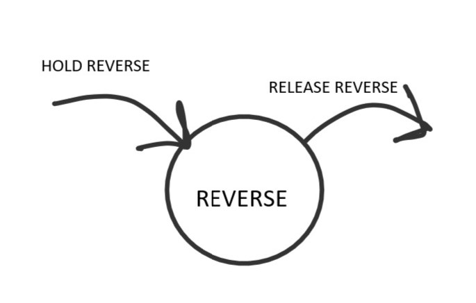
We track the state of the reverse action with the following rule: a hobby-grade RC car reverses when we hold the throttle in reverse and we are not braking. The following diagram illustrates this reverse rule with a caveat: you must track the brake rule at the same time. Use different fingers to follow each diagram as you interact with the transmitter. When the finger tracking the following diagram is over the node “REVERSE” and the other finger is not over the node “BRAKE”, the white leds must turn on.
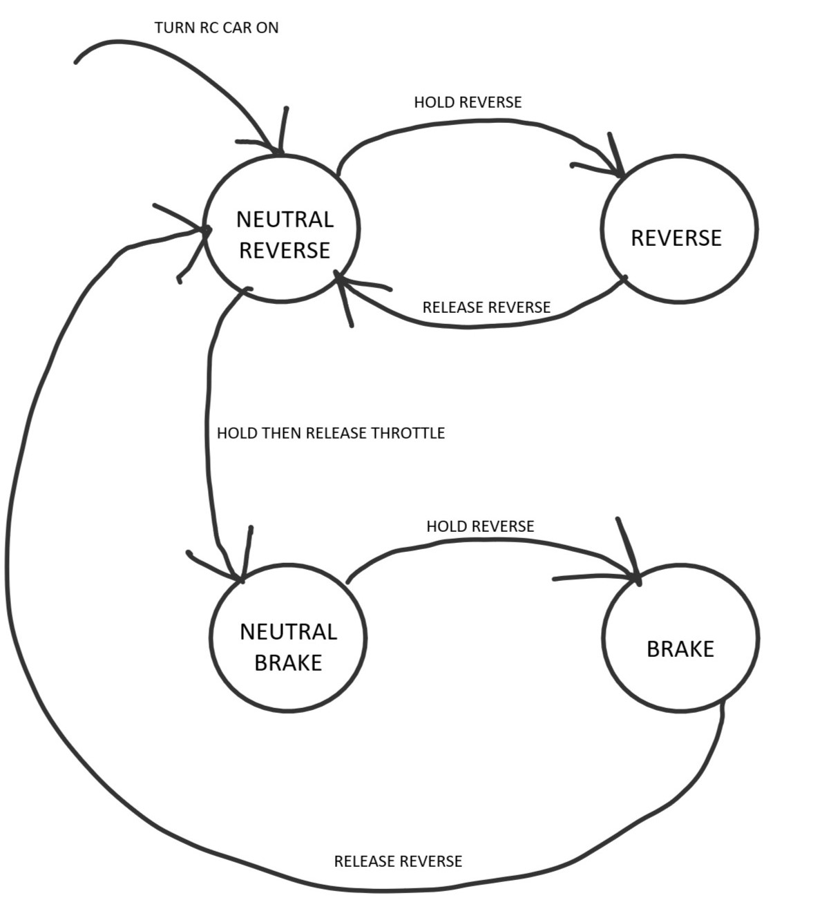
The reason these two rules work and we can track them with two diagrams and two fingers is that the brake action happens only after a very specific event, holding the throttle (forward), and the reverse action happens after either turning on the RC car, braking or reversing as illustrated by the following more verbose diagram. You can track the brake and reverse actions in the verbose diagram with only one finger but implementing the two diagrams above will be significantly easier because they have fewer arrows and nodes.
Sample implementation
We implement the brake and reverse rules in the Radiomaster MT12 with EdgeTX as shown in the following image. The implementation consists of 6 logical switches. Switches L01 to L05 correspond to the brake rule and switch L07 corresponds to the reverse rule.
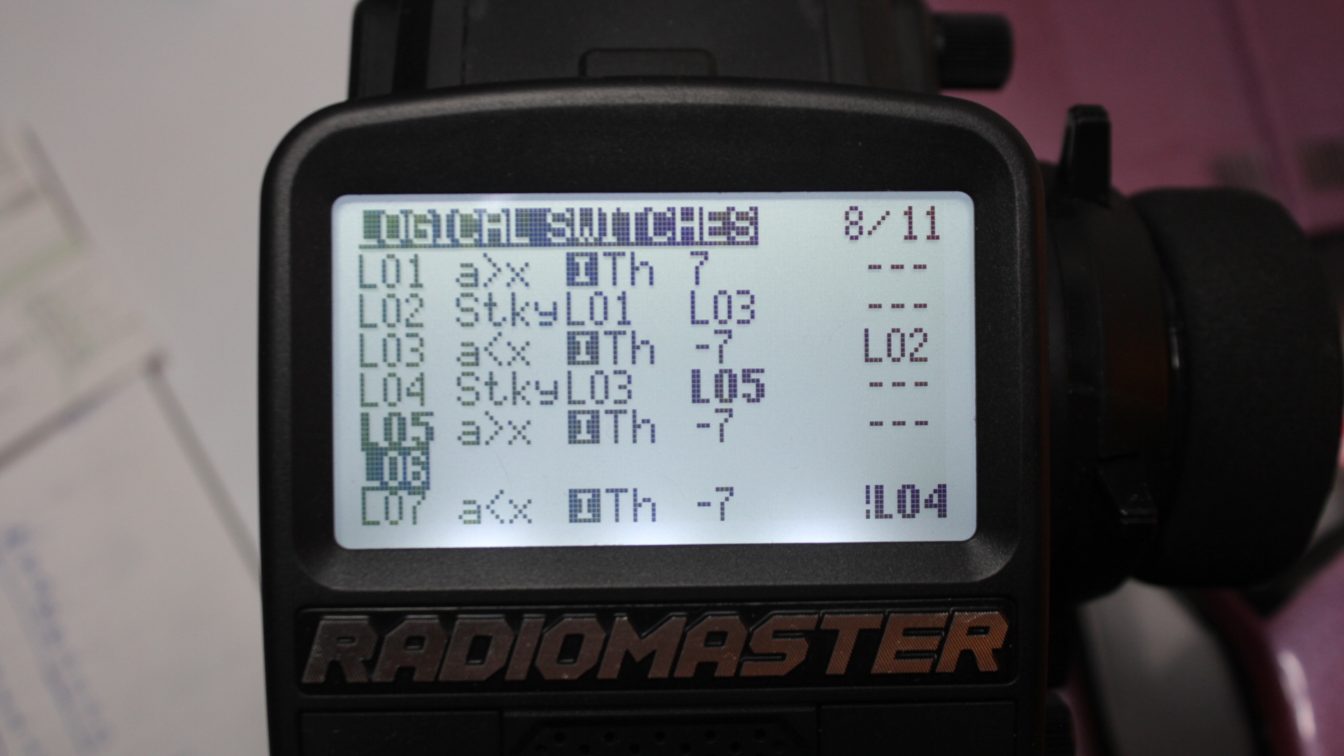
For the case of the brake rule, consider the following annotated diagram. The arrows of the diagram correspond to the inequality switches L01, L03, and L05. For example, switch L01 is true when the throttle position is more than 7 units forward. When a logical switch mentions another logical switch in the last column, the logical switch is true when the inequality is true and the last column is true. For example, switch L03 is true when the throttle position returns to neutral and switch L02 is true. The nodes of the diagram correspond to the sticky logical switches L02 and L04. For example, switch L02 is true after L01 becomes true and until L03 becomes true. The brake action of the RC car happens when L04 is true.

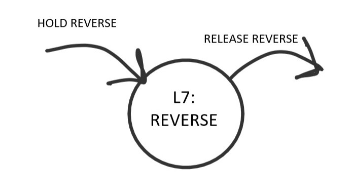
For the case of the reverse rule, consider the following annotated diagram. For this rule it suffices to have the inequality switch L07 be true when the throttle is in reverse more than 7 units and L04 is false. The reverse action of the RC car happens when L07 is true.
The following video shows the activation of switch L07 by going in reverse, and the sequence of activations of switches L01 to L05 when we first go forward and then brake.
So far, we know that the RC car goes in reverse when L07 is true and brakes when L04 is true. The final touch is to convert the activation of L07 into a high state of channel 2 and the activation of L04 into a low state. To do so we mix the logical variables as shown in the following image. Although we use channel 2 in the image, the usual channel for the ESC/motor, a final implementation requires that we control the ESC/motor with one channel and the brake and reverse lights with another because the signals for those components are different.
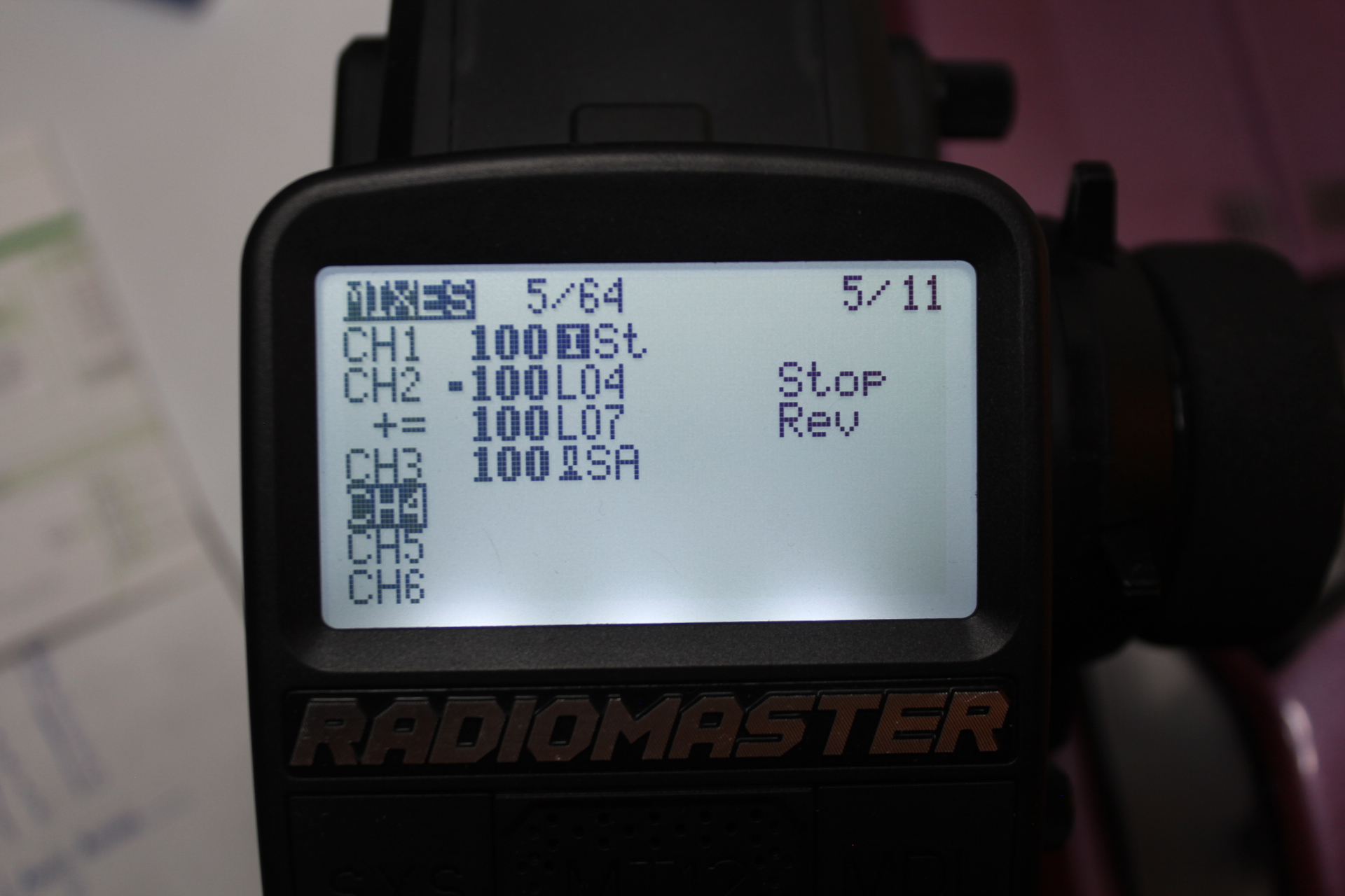
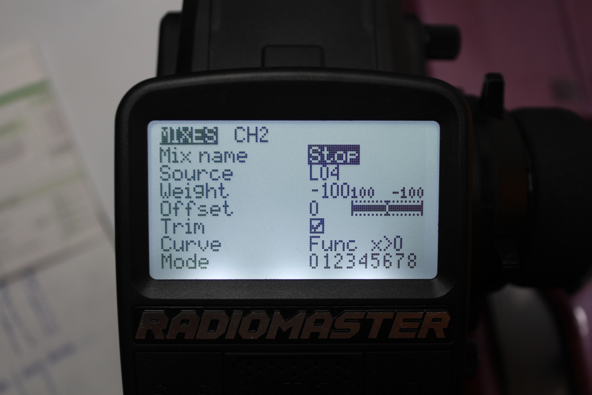
The brake component of channel 2 is negative by setting its weight to -100 as shown in the following image.
The reverse component of channel 2 needs no special treatment to be positive as shown in the following image.
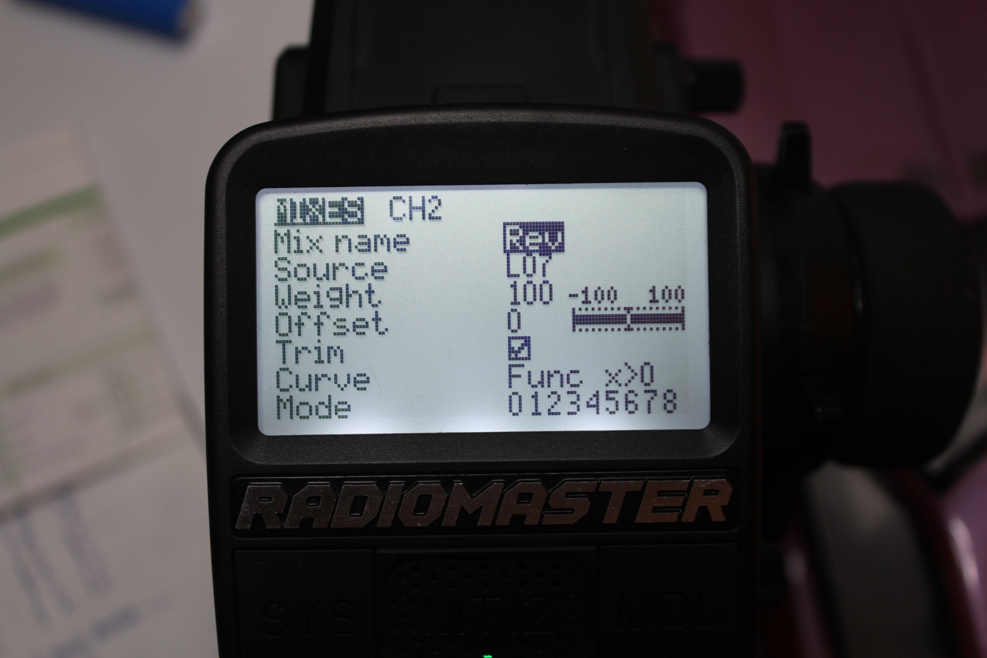
Finally, the implementation of the brake and reverse rules coordinates the led and motor actions in a realistic way.