Raspberry Pico as RC Lights Controller
In this blog post we illustrate how the Raspberry Pico can become an RC car lights controller that is more flexible than the usual Tamiya clone that we presented in the previous post or any similar non-programmable controller.
DISCLAIMER
DISCLAIMER: The contents of this blog post are published with all faults and without any guarantee of any kind and we assume no liability for what you do with anything explained here. Do not try to reproduce anything explained here without adult supervison. If you do try to reproduce anything explained here, do it at your own risk. Working with electronics will expose you to health hazards and potential loss of property, including but not limited to toxic fumes, lead poisoning, and fire hazards. Always wear eye protection and work in a well ventilated area.
Motivation
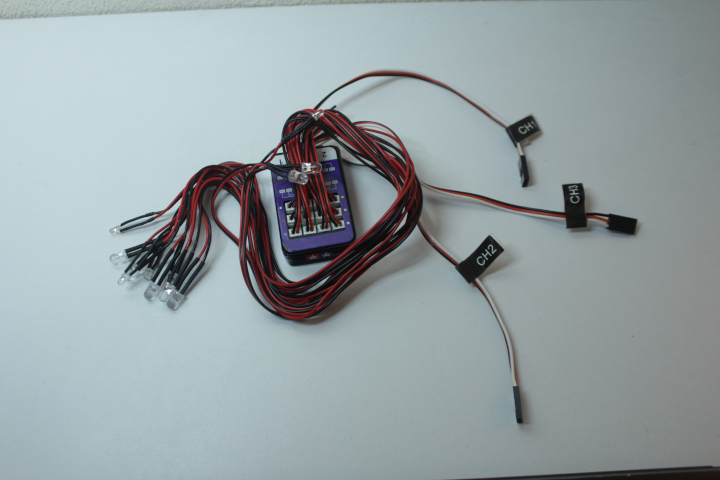
The popular Tamiya light kit for RC cars consists of a controller circuit board connected to some leds and three Dupont connectors, one for each of the three radio receiver channels required to operate it. The following image shows the Tamiya kit.
Although it is possible to control the kit in a more or less realistic way, the kit comes with a fixed set of lights and a fixed set of light states that will not fit all RC car models. This limits the realism that the kit can achieve and also our artistic freedom. When we use a Raspberry Pico as the controller for lights, we become practically unconstrained on the lights and states we can have.
Another problem is that the kit lends itself to be attached to the body shell rather than the chassis of RC cars. It is not uncommon to use a given chassis with different body shells over time. If we want to add lights to more than a couple of body shells, then we will end up spending between 10 to 30 USD for each body shell, depending on where you buy the kit. When we use a Raspberry Pico, we spend a similar amount for the first body shell, and then an order of magnitude smaller amount to add lights to each subsequent body.
Requirements
Given the realism that can already be achieved with the Tamiya kit, we expect that our new Raspberry Pico controller does more. That is, we expect the new controller to do at least the following three things that the Tamiya kit already does.
-
The new controller should be able to turn night lights on/off. Night lights consist of headlights and tail lights.
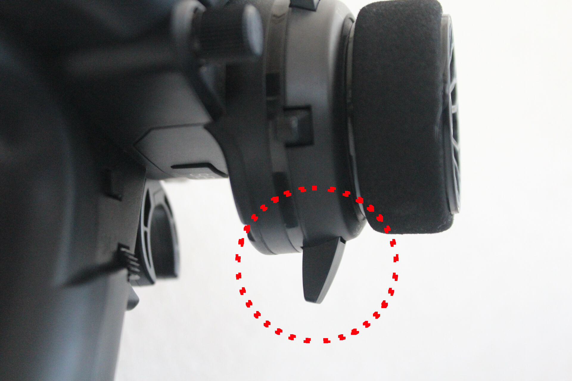
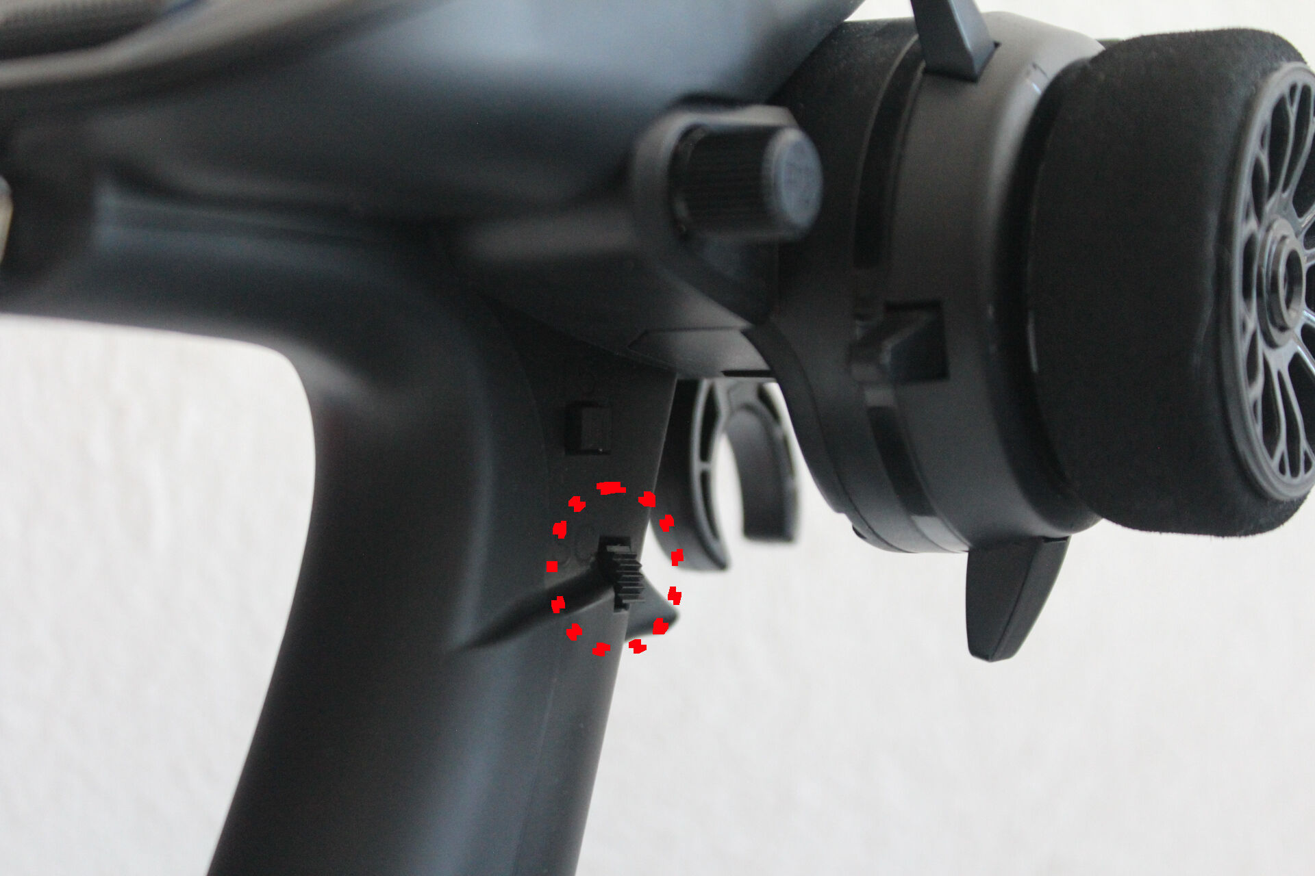
We will ilustrate how to control night lights with a regular switch in our radio transmitter. We’ll be using switch SA of our Radiomaster MT12, which is the following switch. Switch SA is a three-position switch but we will only map one position to “off” and the rest to “on”.
-
The new controller should have left/right blinkers.
We previously controlled blinkers with the steering wheel of our radio transmitter, and we will keep this requirement here too.
-
And finally, the new controller should have working brake and reverse lights.
We previously controlled reverse and brake lights with the throttle trigger of our radio transmitter, and we will keep this requirement here too. Braking and reverse happen under different conditions when we push the trigger forward. Usually an RC car brakes when we push the trigger forwards right after pulling the trigger backwards to accelerate. Also, usually an RC car moves in revers when we push the trigger forwards right after braking.
Additionally, the new controller must do the following five things that we cannot do with the Tamiya kit.
-
The new controller must use only one communication channel instead of 3. The following image shows the three Dupont connectors of the Tamiya light kit using valuable channel sockets of a radio receiver. We could be using some of the channels for other things.

The new controller should only have one Dupont connector that we use to connect only one channel of a given radio receiver, as in the following image, and then the controlling of the lights should happen over that single channel.
-
When we turn on night lights, the tail lights turn on. Also, when night lights are on and we brake, the tail lights go from on to high. The following video illustrates this new feature.
Using the same set of lights as regular tail lights and brake lights cannot be achieved with the Tamiya light kit because that kit has two independent sets of red lights for the rear of the RC car, one that turns on when the night lights are on and one that turns on only when we brake.
-
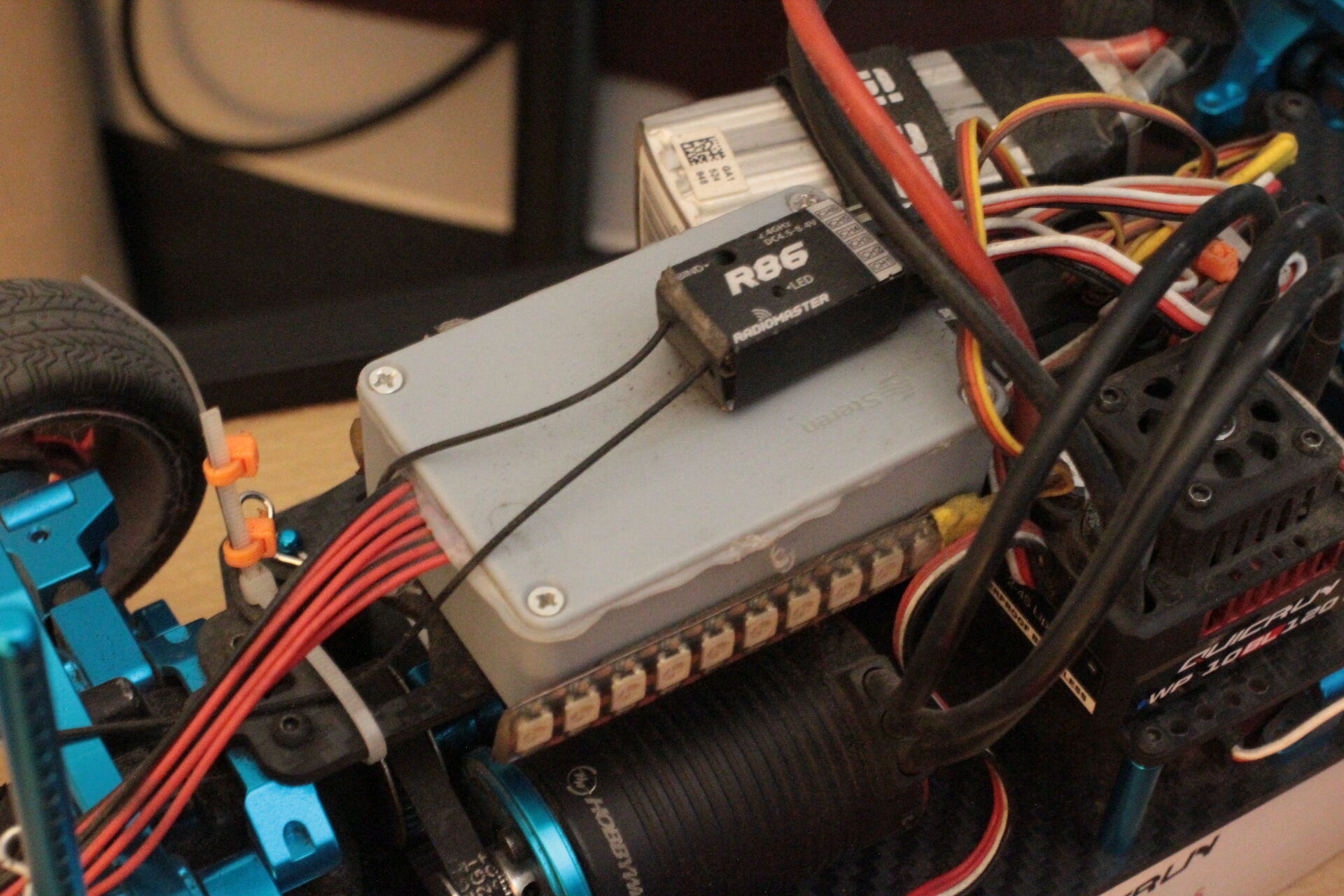
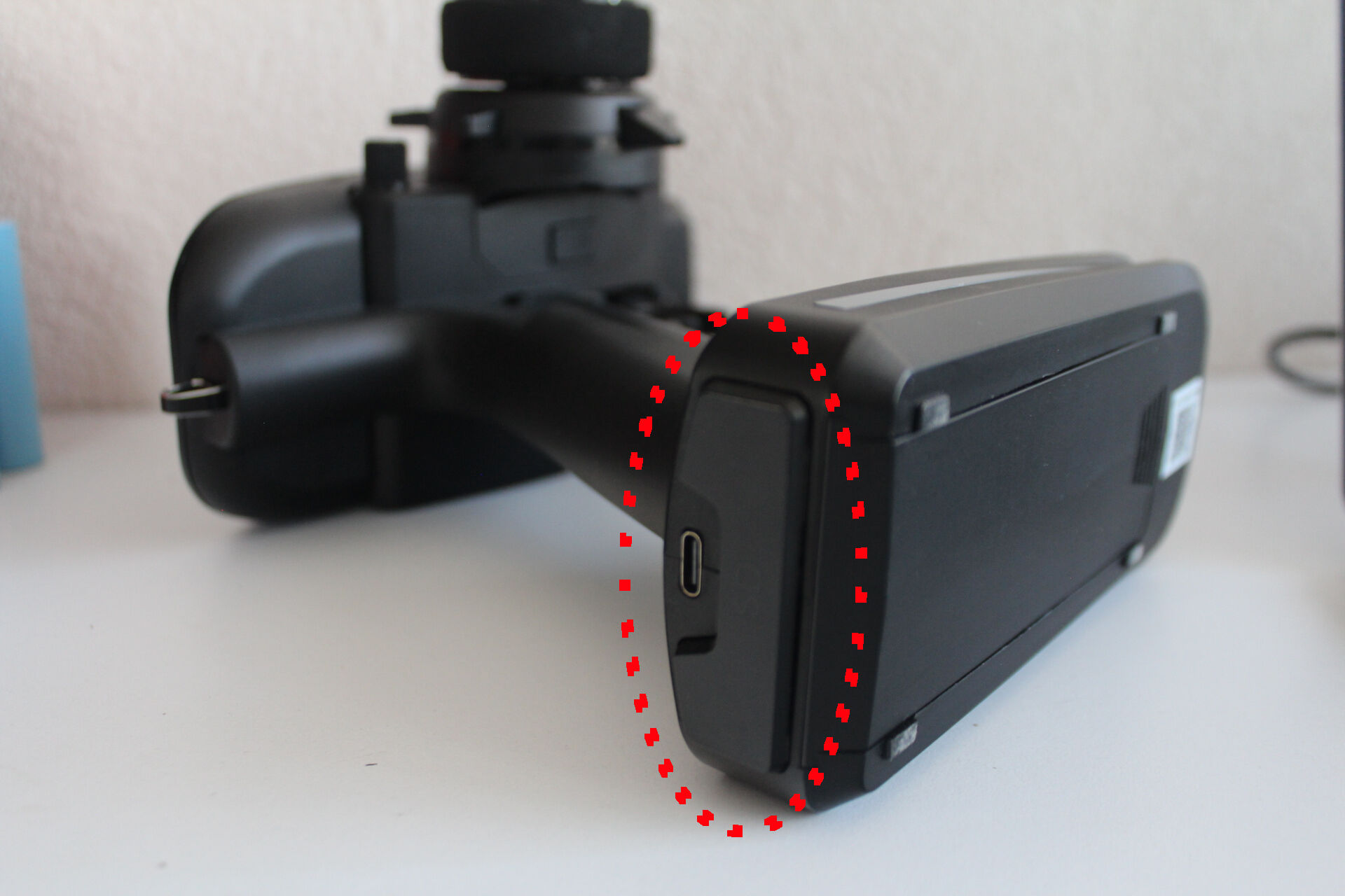
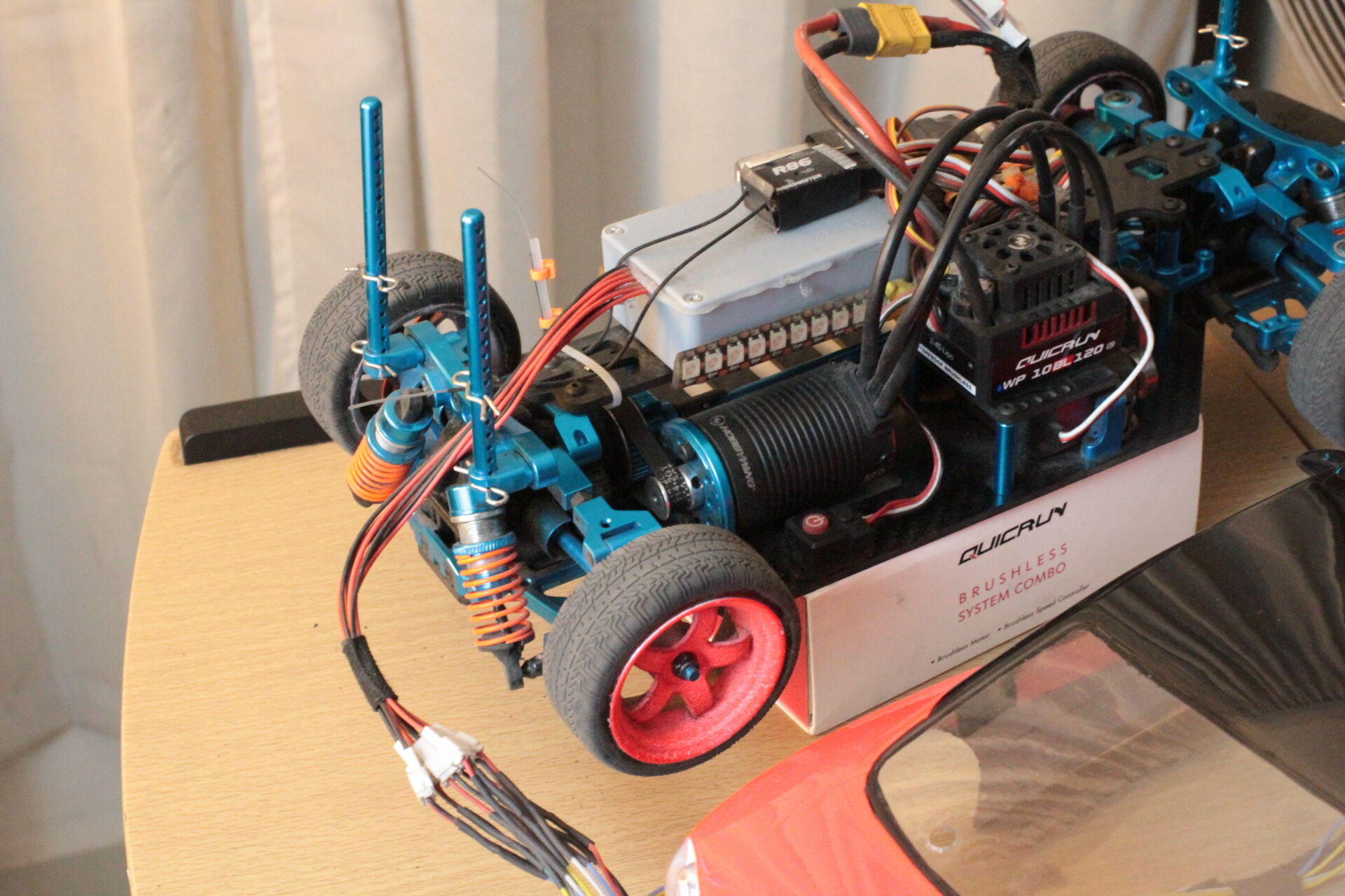
The color, number and position of lights is a concern of the body, power and control is a concern of the chassis, so the controller must remain attached to the chassis across body changes. The following image shows the new controller attached to the chassis of our RC car.
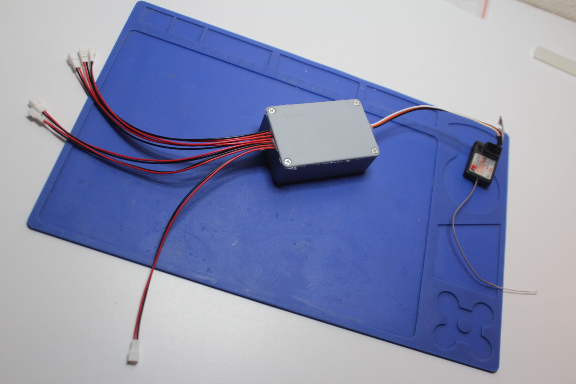
The lights remain on the body shell. The lights are connected to the new controller by a wire loom that can be easily disconnected as the depicted in the following image. The loom consists of several pairs of wires, each corresponding to one connector in the following image, and each corresponding to one or more leds in the body shell. The new controller provides enough current to drive several leds per pair of wires but the body shell is responsible for providing the resistors that correspond to the number and kind of leds connected to a given pair.

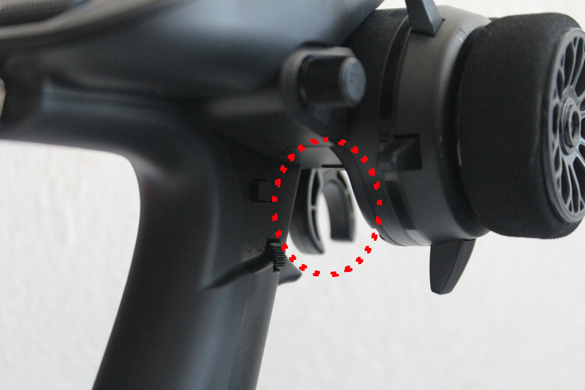
As an implementation detail, the wire loom should be long enough to facilitate servicing without disconnecting the chassis and the body shell, as illustrated in the following image.
-
As a nice to have, blinkers should double as hazard lights.
We will use the momentary switch SD of our Radiomaster MT12 radio transmitter to toggle hazard lights on and off.
-
As another nice to have, headlights should have a high beam feature.
We will use the momentary switch SC of our Radiomaster MT12 radio transmitter to toggle high beams on and off.
Approach
Our approach to controlling the lights of our RC car in the way we want consists of the following three steps.
- Encode physical inputs as a PWM signal over a single channel.
- Decode that PWM signal into its components.
- Control each set of lights according to those components.
To illustrate our approach, we group the lights installed in our RC car in the following light sets. Some concrete lights might be included in more than one light set.
-
Night lights consists of head lights and stop lights. The state of these lights is on or off depending on the position of the switch SA. Although switch SA is a three-position switch, we consider the first position to be off and the other two to be on.
-
High beams consists of head lights. The state of high beams is either “on” or “don’t care”. They become “on” when we toggle momentary switch SC and what this means is that the head lights become brighter than when we turn night lights on. High beams become “don’t care” when we toggle momentary swich SC again and what this means is that the head lights become the state indicated by any other light set.
-
Blinkers consists of the left and right blinkers. The state of the blinkers is either off, “left”, “right”, or “hazard”. They become “left” or “right” when we turn left or right. They become “hazard” when we toggle the momentary switch SD. They remain off otherwise.
-
Brake & Reverse consists of the tail lights and the reverse lights. The state of this light set is either “reverse”, “brake”, or “off”. State “reverse” means that the reverse lights are on and the tail lights are “don’t care”, meaning that the tail lights do whatever any other light set indicates or remain off. State “brake” means that tail lights become high, that is brighter than when we turn night lights on, and reverse remains off. State “off” means that reverse lights are off and stop lights are “don’t care”. Keep in mind that the reverse lights cannot be on and the tail lights cannot be high at the same time because the reverse and brake actions are mutually exclusive.
Given the light sets of our RC car, there are 48 different combinations of light set states as illustrated by the following table. We call each of these combinations a master state. We also assign indices to light set states to refer to them later.
Light Set | Count of states | States and their indices
---------------------------------------------------------
night     |        2        | 0:off, 1:on
hi-beams  |        2        | 0:"don't care", 1:"on"
blinkers  |        4        | 0:off, 1:"left", 2:"right", 3:"hazard"
rev-brake |        3        | 0:"off", 1;"brake", 2:"reverse"
Encode physical inputs as a PWM signal
Consider the concept of duty cycle in PWM signals. We encode different combinations of physical inputs as different duty cycles representing master states in the following way.
Our Radiomaster MT12 radio transmitter abstracts the duty cycle as a value ranging from -100 integer units to 100 integer units. Let’s call these units duty cycle units or DCU. Duty cycle units are always integers, never real numbers, therefore there are 201 duty cycle units in the closed interval [-100, 100] as illustrated by the following diagram.
                                                  1 duty cycle unit
                                                    |
                                                    v
  |<----------- 100 duty cycle units ------------->| |<---------- 100 duty cycle units -------------->|
  |-------------------------------------------------|-------------------------------------------------|
-100                                                0                                                100
To represent 48 master states, we place an id(entification number) for each state as evenly and as far apart as possible. Ids start from zero. All the intervals are 4 duty cycle units long except the interval that starts with id 24 and ends with id 25 which consists of 5 duty cycle units because it consists of duty cycle units -2, 1, 0, 1, and 2.
                         10                  20                  30                  48                   <---- Master state ids
     0 1 2 3 4 5 6 7 8 9 | 1 2 3 4 5 6 7 8 9 | 1 2 3 4 5 6 7 8 9 | 1 2 3 4 5 6 7 8 9 | 1 2 3 4 5 6 7      <---- Master state ids
     | | | | | | | | | | | | | | | | | | | | | | | | | | | | | | | | | | | | | | | | | | | | | | | |
  |-------------------------------------------------|-------------------------------------------------|
-100                                                0                                                100  <---- duty cycle units
   | | | | | | | | | | | | | | | | | | | | | | | | | | | | | | | | | | | | | | | | | | | | | | | | | |
   8 4 0 6 2 8 4 0 6 2 8 4 0 6 2 8 4 0 6 2 8 4 0 6 2 2 6 0 4 8 2 6 0 4 8 2 6 0 4 8 2 6 0 4 8 2 6 0 4 8    <---- duty cycle units
       |    |    |    |    |    |    |    |    |         |    |    |    |    |    |    |    |    |
      -90  -80  -70  -60  -50  -40  -30  -20  -10        10   20   30   40   50   60   70   80   90       <---- duty cycle units
Then, we assign master states to ids as indicated by the following diagram. For example, master state id 20 indicates that the state of light set Brake & Reverse is 2 (“reverse”), the state of light set Blinkers is 2 (“right”), the state of light set High Beams is 1 (“on”), and the state of Night Lights is 0 (off).
     0 1 2 0 1 2 0 1 2 0 1 2 0 1 2 0 1 2 0 1 2 0 1 2 0 1 2 0 1 2 0 1 2 0 1 2 0 1 2 0 1 2 0 1 2 0 1 2      <---- rev-brake
     0 0 0 1 1 1 2 2 2 3 3 3 0 0 0 1 1 1 2 2 2 3 3 3 0 0 0 1 1 1 2 2 2 3 3 3 0 0 0 1 1 1 2 2 2 3 3 3      <---- blinkers
     0 0 0 0 0 0 0 0 0 0 0 0 1 1 1 1 1 1 1 1 1 1 1 1 0 0 0 0 0 0 0 0 0 0 0 0 1 1 1 1 1 1 1 1 1 1 1 1      <---- hi-beams
     0 0 0 0 0 0 0 0 0 0 0 0 0 0 0 0 0 0 0 0 0 0 0 0 1 1 1 1 1 1 1 1 1 1 1 1 1 1 1 1 1 1 1 1 1 1 1 1      <---- night lights

                         10                  20                  30                  48                   <---- Master state ids
     0 1 2 3 4 5 6 7 8 9 | 1 2 3 4 5 6 7 8 9 | 1 2 3 4 5 6 7 8 9 | 1 2 3 4 5 6 7 8 9 | 1 2 3 4 5 6 7      <---- Master state ids
     | | | | | | | | | | | | | | | | | | | | | | | | | | | | | | | | | | | | | | | | | | | | | | | |
  |-------------------------------------------------|-------------------------------------------------|
-100                                                0                                                100  <---- duty cycle units
   | | | | | | | | | | | | | | | | | | | | | | | | | | | | | | | | | | | | | | | | | | | | | | | | | |
   8 4 0 6 2 8 4 0 6 2 8 4 0 6 2 8 4 0 6 2 8 4 0 6 2 2 6 0 4 8 2 6 0 4 8 2 6 0 4 8 2 6 0 4 8 2 6 0 4 8    <---- duty cycle units
       |    |    |    |    |    |    |    |    |         |    |    |    |    |    |    |    |    |
      -90  -80  -70  -60  -50  -40  -30  -20  -10        10   20   30   40   50   60   70   80   90       <---- duty cycle units
Master states that transition between each other frequently are close to each other in the previous diagram to avoid as much as possible any delay incurred by our radio transmitter when it moves from one duty cycle to another. For example, reverse and brake lights turn on and off frequently and thus master states that change these lights but keep the rest the same are close neighbors. Another example, night lights seldom change state, so half of the duty cycle range corresponds to the off state and the other to the on state.
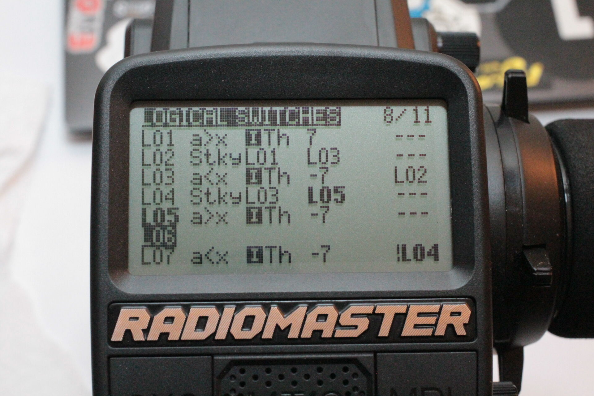
Following the distribution of master states over the duty cycle range, we capture physical interactions with the radio transmitter in 6 logical switches that we mix in a single channel in the way shown in the following image.
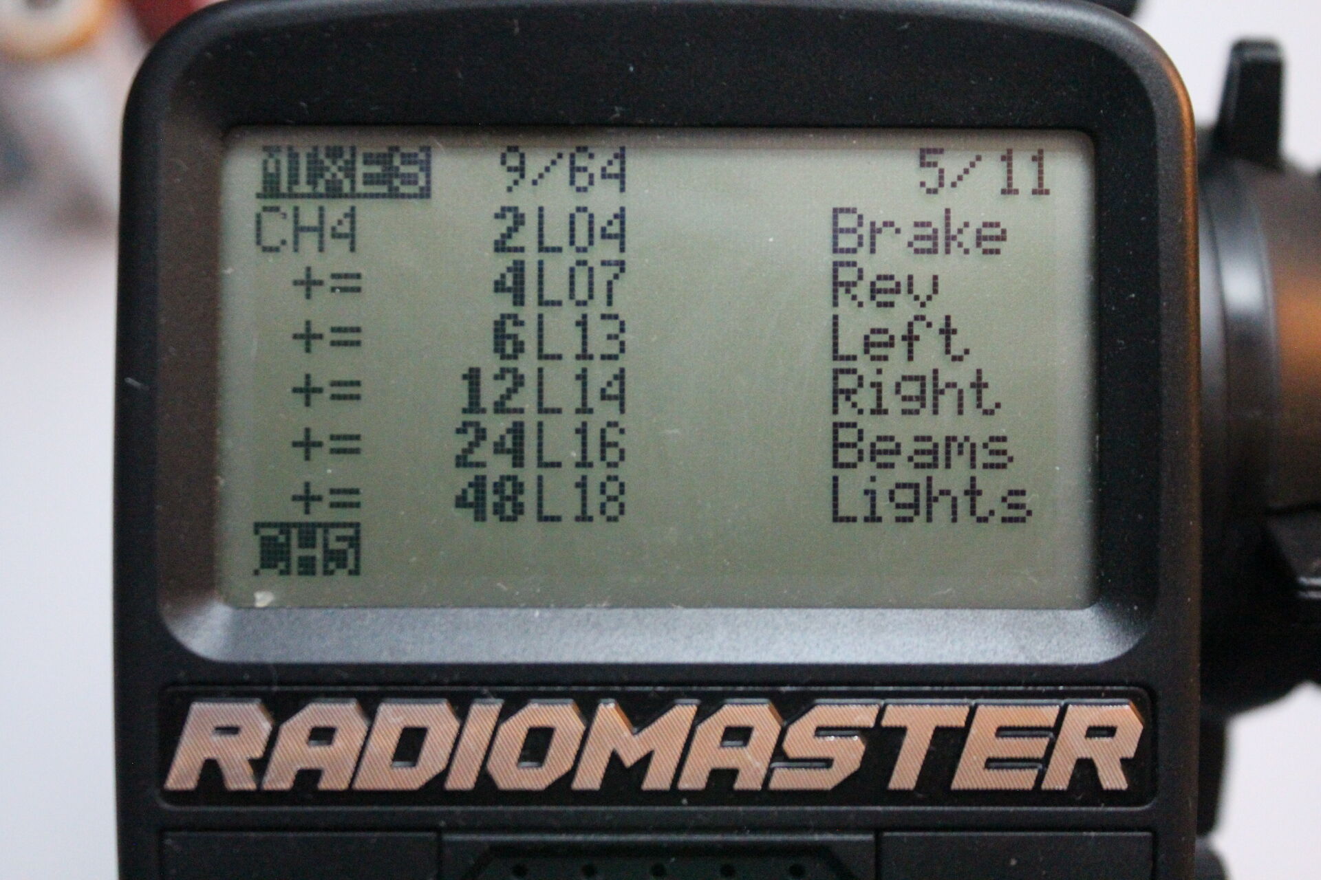
One question we could ask is: why not use powers of 2 for the commponents of the mix as opposed to having a weird component called “Rev” with a weight of 3 duty cycle units? Doing so would mean we would place 64 labels over the duty cycle range and 16 of those labels would not correspond to any master state.
The capturing of physical actions as mix components increases in complexity from bottom to top in the previous image. The explanation for each mix component is the following.
-
Night lights. We interpret switch SA as a mix component of -48 for the off state of night lights or 48 for the on state. Because the switch SA is a three-position switch, logical variable L18 maps the first position to off and the other two to on as follows.
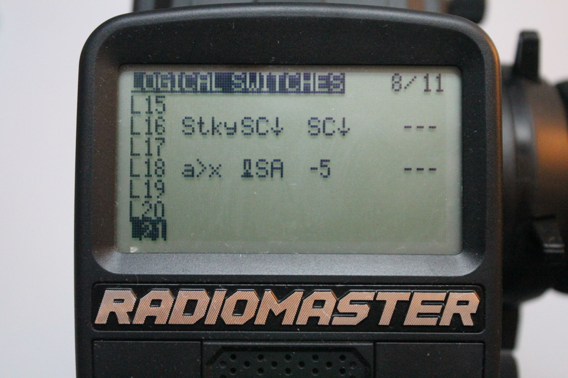
Then, the mix component for night lights feeds from L18 and has a weight of 48 duty cycle units as follows.
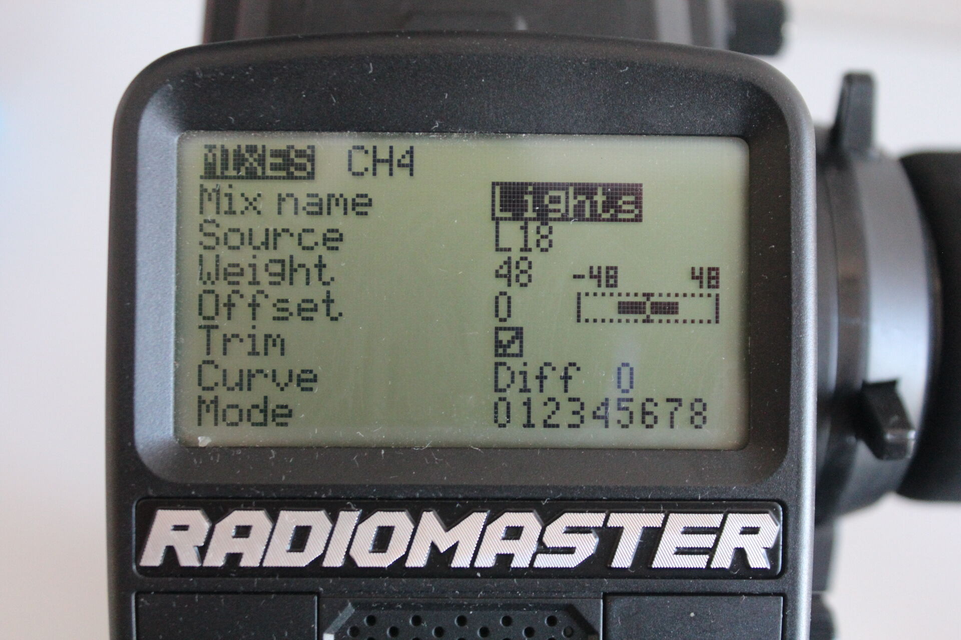
The mix component maps the off value of L18 to -48 duty cycle units, which puts the value of the channel in the lower half of the duty cycle range. When L18 is on, the value of the channel moves towards the upper half of the duty cycle.
-
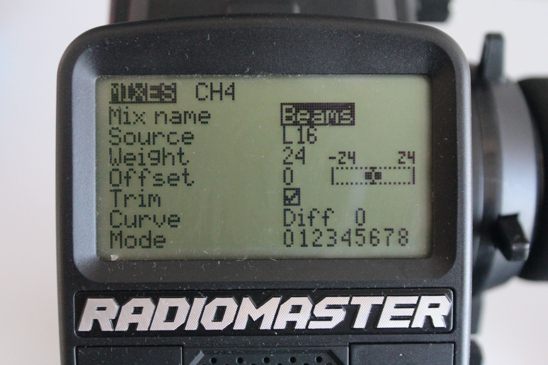
High Beams. We interpret momentary switch SC as a toggle switch using logical switch L16 as in the image bellow. A toggle switch is one that turns on with one press and release, and then turns off with the next press and release.
Then we feed L16 into the a mix component with weight 16 duty cycle units so that given the half of the range indicated by the night lights mix, we move the duty cycle to either the upper or lower quarter of that half of the range.
-
Blinkers. We represent the four states of light set Blinkers with two logical switches L13 and L14 defined as shown in the following image.
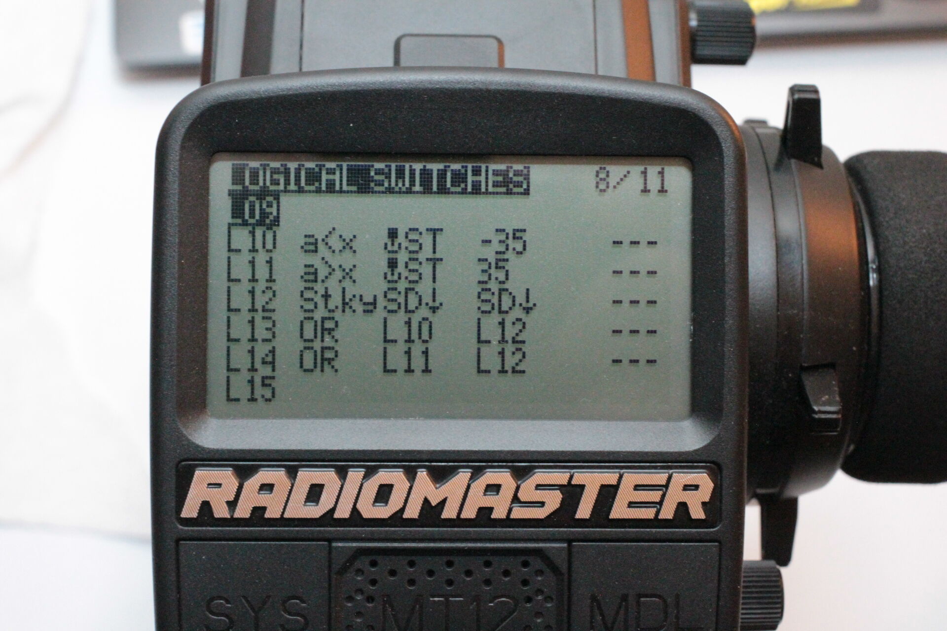
When we turn the steering wheel of the radio transmitter, only one or the other logical switch becomes on, signaling to turn only the left or right blinkers. When we toggle momentary switch SD an odd number of times, both logical switches become on, signaling that hazard lights are on. Otherwise both switches are off.
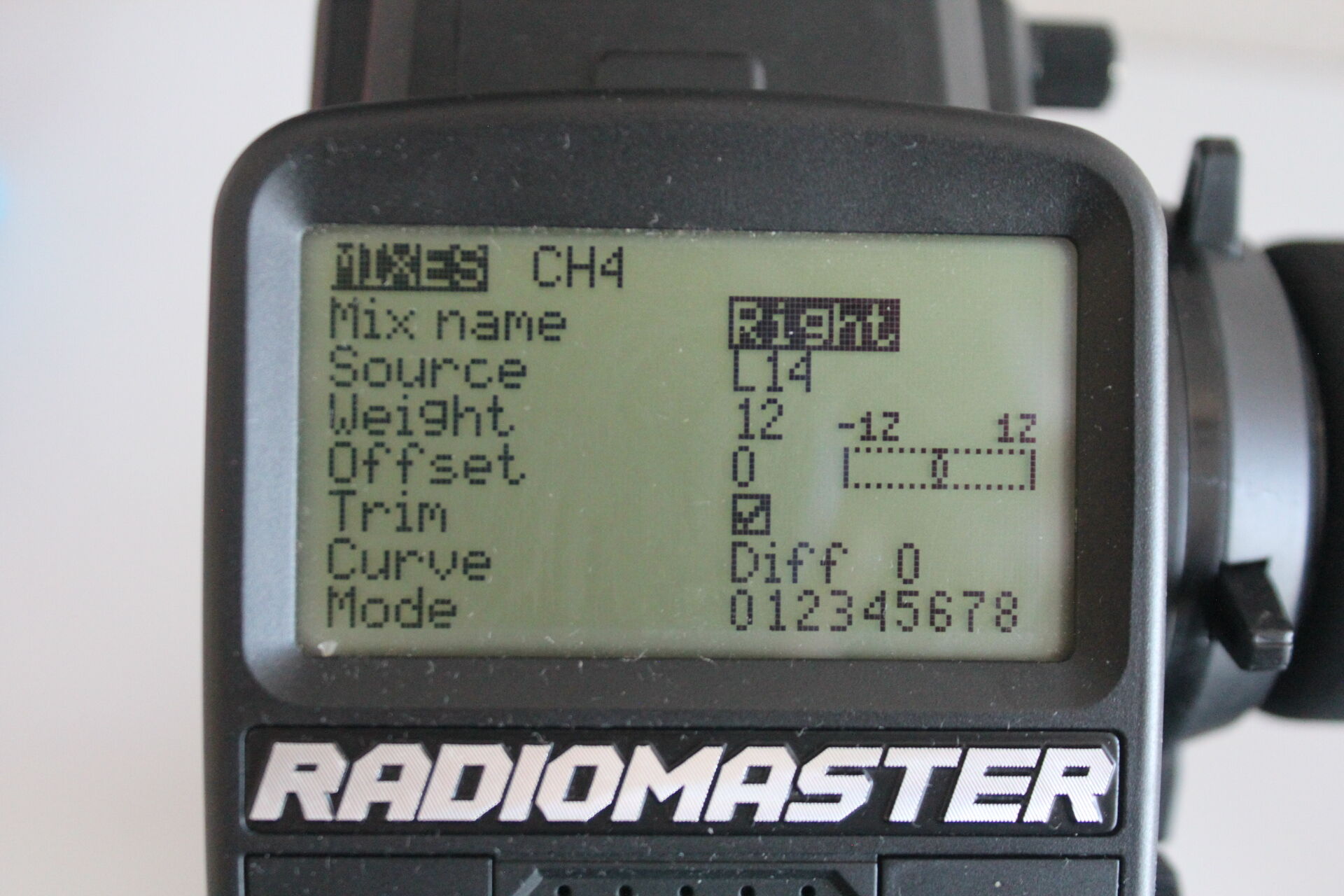
Because logical switches L13 and L14 make four combinations, we further divide the quarter of the duty cycle indicated by the light set High Beams by feeding each one into a separate mix component as shown in the following two images and thus dividing the duty cycle first in 8 parts and then in 16.

-
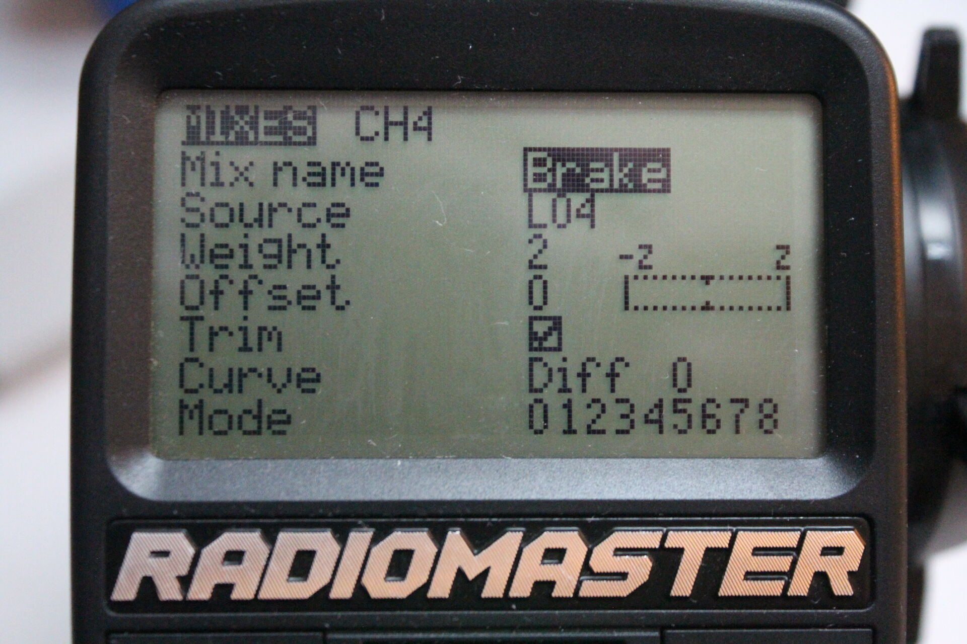
Brake & Reverse. The most challenging of the mix components. Light set Brake & Reverse is represented by two different logical switches L04 (brake) and L07 (reverse) which are mutually exclusive. They are configured as shown in the following image. In our previous post we explain why this configuration works.
Because L04 and L07 are mutually exclusive, only the following three combinations are possible, which should cause the PWM duty cycle transmitted to the RC car to either remain where it is indicated by all the previous mixes (state 1 corresponding to braking), move 4 duty cycle units (DUC) to the left (state 0 corresponding to neither braking nor reversing) or 4 units to the right (state 2 corresponding to reversing).
   State | L04 (brake) | L07 (reverse) | duty cycle units
  -------|-----------------------------------------------
     0   |      0      |       0       |        -4
     1   |      1      |       0       |         0
     2   |      0      |       1       |         4
One way of mapping each of the previous combinations of L04 and L07 is to assign a weight of 2 duty cycle units to L04 and to assign 4 duty cycle units with an offset of 2 to L07 as shown in the following two images.
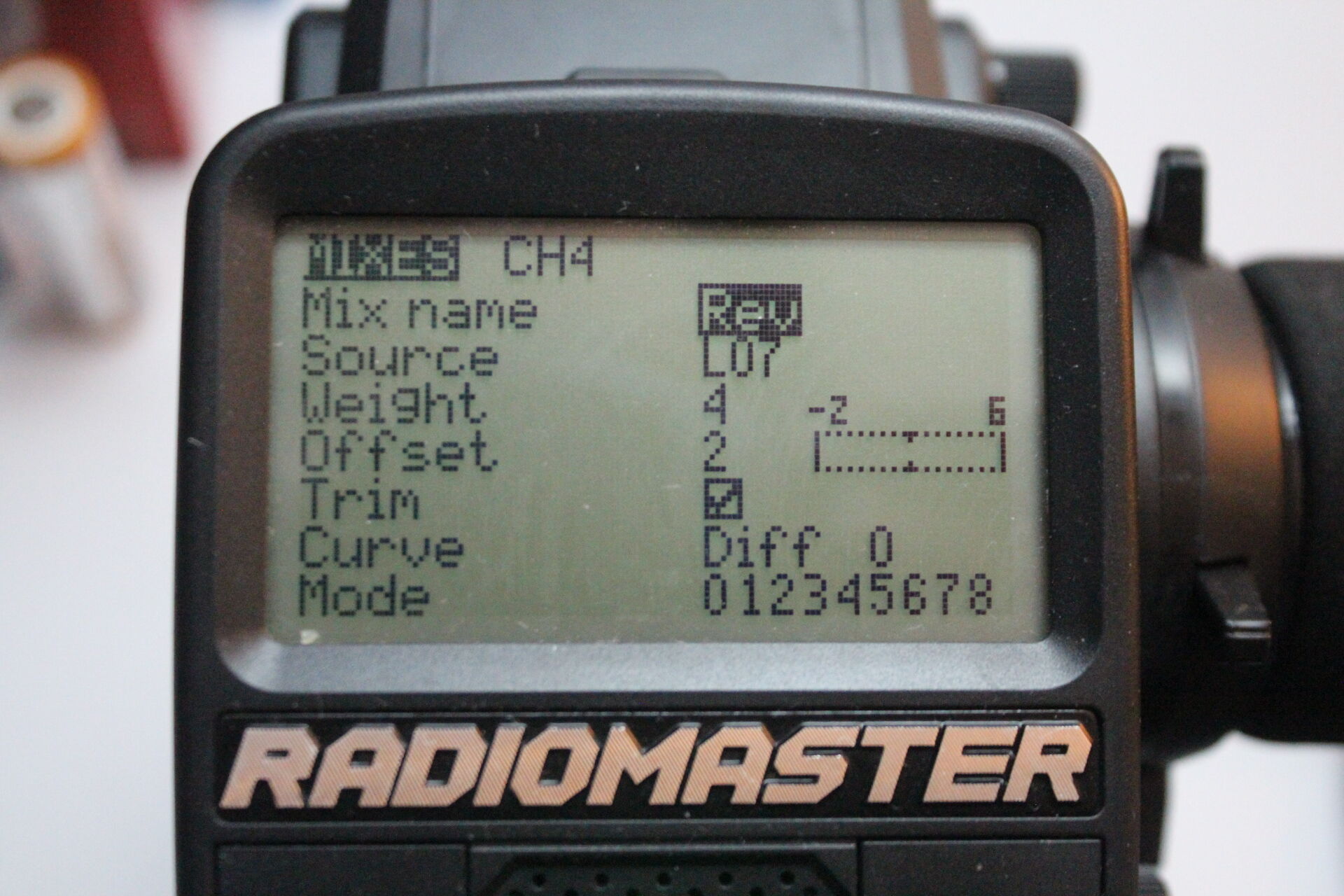
This works because the sum of the mix component Brake and mix component Rev give the duty cycle units we expected for each state.
   State | L04 (brake) | L07 (reverse) | mix Brake DCU | mix Rev DCU | Brake + Rev DCU
  -------|-----------------------------------------------------------|-----------------
     0   |      0      |       0       |      -2       |     -2      |       -4
     1   |      1      |       0       |       2       |     -2      |        0
     2   |      0      |       1       |      -2       |      6      |        4
Read input PWM
To decode the PWM signal broadcasted by our radio transmitter, we determine the master state corresponding to the duty cycle of the signal and then we project the master state into the individual state for each light set. We do so as follows.
-
Determine master state for input PWM. When we divided the radio transmitter duty cycle range into 201 integral units, we mentioned that the interval that contains position 0 is 5 duty cycle units long instead of 4 duty cycle units long as the rest of the intervals. In practice we can ignore this property of the way we have encode our master states and regard all intervals as equal length with the following assignment in the C programming language.
const float INPUT_PWM_US_BUCKET_SIZE = (INPUT_PWM_US_MAX - INPUT_PWM_US_MIN + 1) / (MASTER_LIGHT_STATE_COUNT - 1);The way to read the previous assignment is the following. All the identifiers on both sides of the equation are floating point. Constants
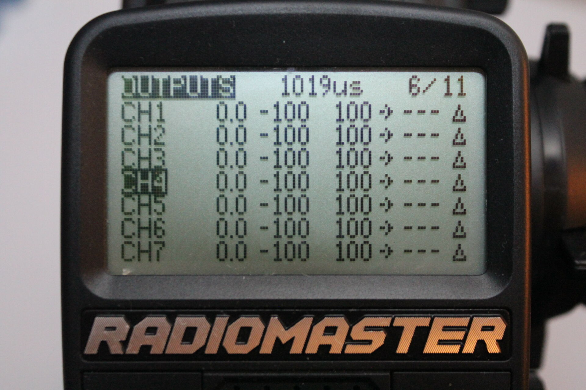
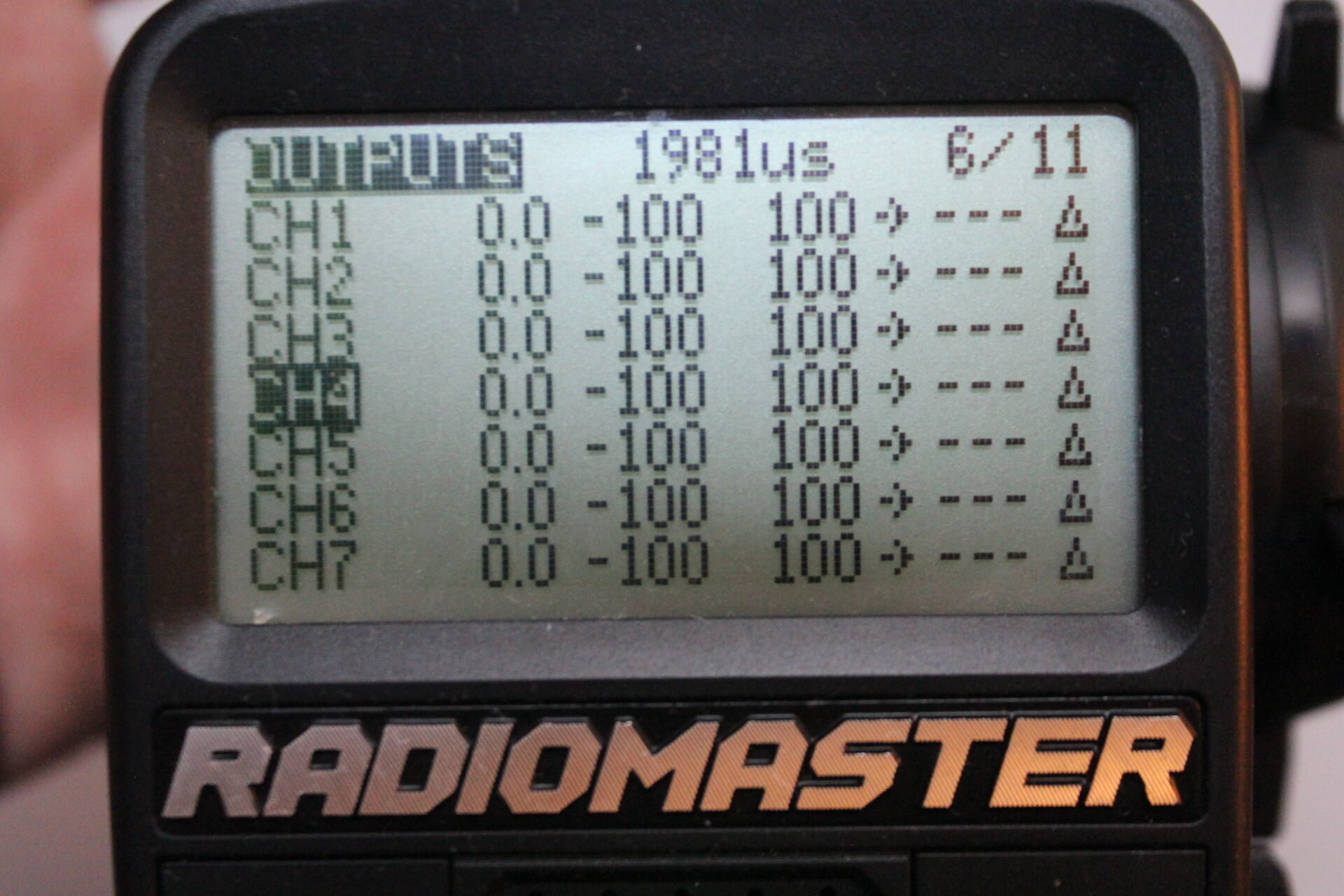
INPUT_PWM_US_RANGE_MINandINPUT_WPM_US_RANGE_MAXindicate the minimum and maximum value of the duty cycle range in microseconds instead of duty cycle units. Because we consider 48 master states, constantMASTER_LIGHT_STATE_COUNTequals 48. However, there are only 47 intervals between each of the master state ids we have placed over the duty cycle range, and thus we divide the length of the range, from min to max inclusive, over 47.A crucial aspect of the previous formula is finding the minimum and maximum duty cycle values in microseconds. In the case of the radio transmitter we are using, the Radiomaster MT12, we can find these values from the OUTPUTS configuration page by turning all light sets to the off position and then turning each lights set to the state that gives the maximum corresponding mix value. The maximum and minimum values for our transmitter are shown on the top center of the following two images.
Given the interval size, we compute the master state id with the following assignment in the C programming language.
uint8_t master_state_id = (duty_cycle_us - INPUT_PWM_US_RANGE_MIN + INPUT_PWM_US_BUCKET_SIZE / 2) / INPUT_PWM_US_BUCKET_SIZE;The way to read the previous formula is the following. All the identifiers on the right hand side of the equation are floating point and correspond to values in microseconds. Variable
duty_cycle_usindicates the current duty cycle in microseconds. The variablemaster_state_idbecomes an integer between 0 and 47 inclusive, so one of 48 values, one for each master state. This happens by shiftingduty_cycle_usto the beginning of the duty cycle rangeINPUT_PWM_US_RANGE_MIN, and adding half an interval as padding to disambiguate the interval where the shifted duty cycle falls into. Dividing by the interval size gives a floating value between 0 and 48 exclusive, then assigning to an unsigned integer has the effect of truncating the floating value. For example, when the input duty cycle in microseconds is 1981, the floating value of the right hand side of the assignment is approximately ~47.45119418483904465213, which truncates to 47, the biggest master state id.Given the master state id, an integer between 0 and 47 inclusive, the following assignment in the C programming language produces a binary representation of the master state.
uint8_t master_state = (state_id % 3) + ((state_id / 3) << 2)For example, consider master state id 20 and its 8-bit binary representation
00010100. Because we go over all the three states of light set Brake & Reverse for every three master state ids, we obtain the state id of that light set by taking the modulo of dividing 20 over 3, which is 2 (in binary10) and corresponds to state “reverse”. Because the rest of the light sets change state after every three master state ids, we keep the integer division of 20 over 3 as the rest of the bits for the master state by shifting it 2 bits to the left, in this case 20 / 3 = 6 in binary110. Finally, the master state becomes11010and consists of the concatenation of110followed by the Brake & Reverse part10. -
Determine individual light set states. Given the binary representation of a master state, the following assignments in the C programming language calculate the individual state id for each light set.
  uint8_t brake_light_state = master_state & 1;
  uint8_t reverse_light_state = (master_state >> 1) & 1;
  uint8_t blink_light_state = (master_state >> 2) & 3;
  uint8_t hi_beams_state = (master_state >> 4) & 1;
  uint8_t day_night_state = (master_state >> 5) & 1;
For example, for master state id 20 and the binary representation of its corresponding master state
11010, first two bits from right to left indicate the state id for the light set Brake & Reverse, in this case10or state 2. The next two bits moving to the left indicate the state id for the light set Blinkers, in this case10or state 2. The next bit moving to the left indicates the state of light set High Beams, in this case state 1. Finally the next bit to the left, which is an implicit zero, indicates that the state id of light set Night Lights is 0.
Implementation
We implement our approach using as radio transmitter a Radiomaster MT12 and as lights controller a Raspberry Pico that we program using the C programming language.
The program that drives the Raspberry Pico is available on GitHub. The program consists of a main loop that does the following.
- Read input PWM
- Convert to master state
- Apply master state to light sets
Instead of a main loop, one could use the Raspberry Pico facilities for programming interrupt handlers. We leave this as an exercise to the reader.
We wire the Raspberry Pico as indicated by the following diagram.
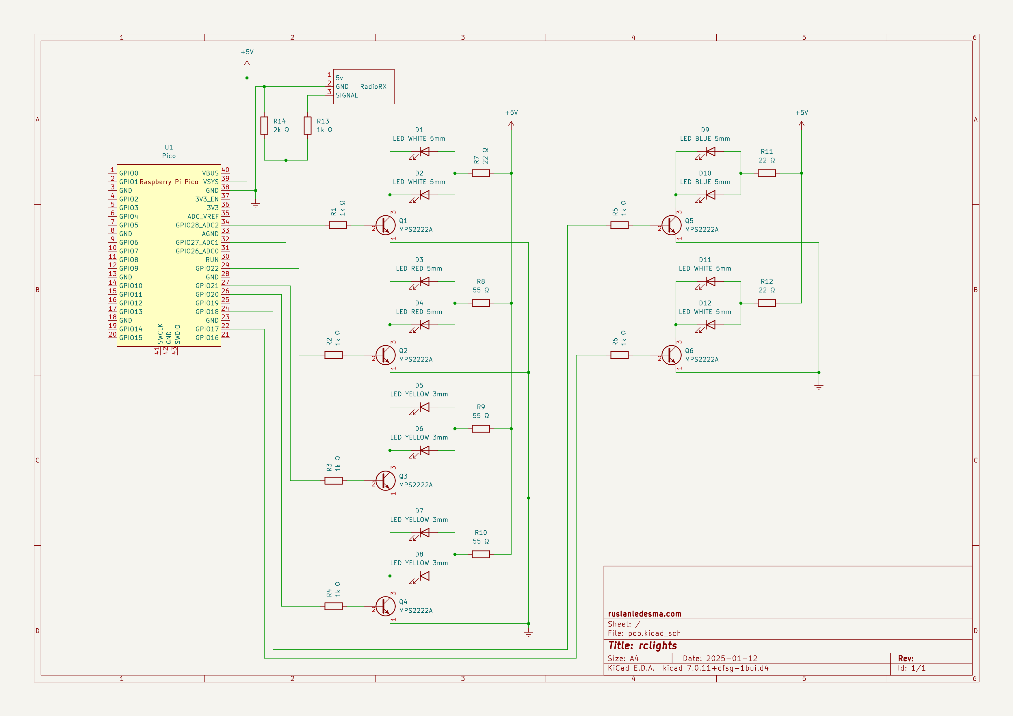
Our wiring of the Raspberry Pico takes into account the following considerations.
- The Raspberry Pico is limited to about 12mA per GPIO and the sum of the output currents of all GPIOs should not exceed 50mA (see sections 5.5.3.4 and 5.5.3.5 of the RP2040 datasheet). Therefore, we use transistors to increase the current delivered to the leds of the car.
- The Raspberry Pico can be powered using 5v (see section 4.5 of the Raspberry Pico datasheet) but the GPIOs accept up to 3.3v + 0.3v = 3.6v (see section 5.5.3.4 of the RP2040 datasheet). For this reason we power the Raspberry Pico directly from 5v but we use a voltage divider to drop the voltage that the signal pin of the radio receiver imparts on GPIO 27 (pin 32).
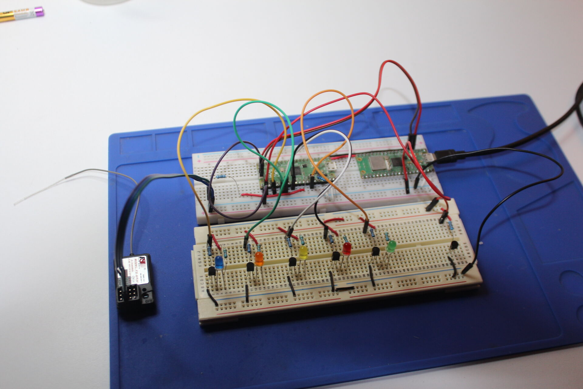
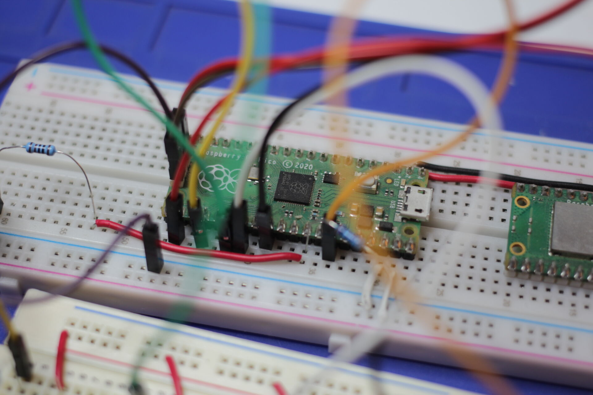
We develop and test our wiring and our program with the help of a second Raspberry Pico as shown in the following two pictures (see section “Debug with a second Pico or Pico 2” in the Raspberry Pico getting started guide).
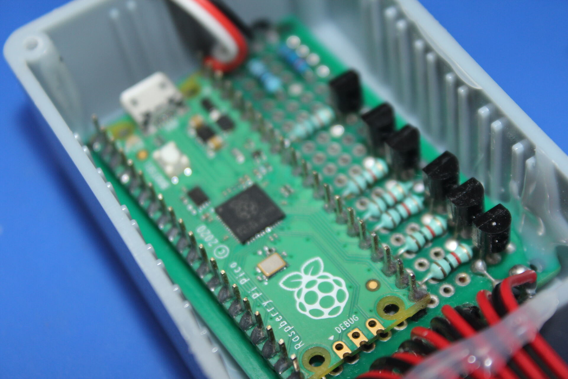
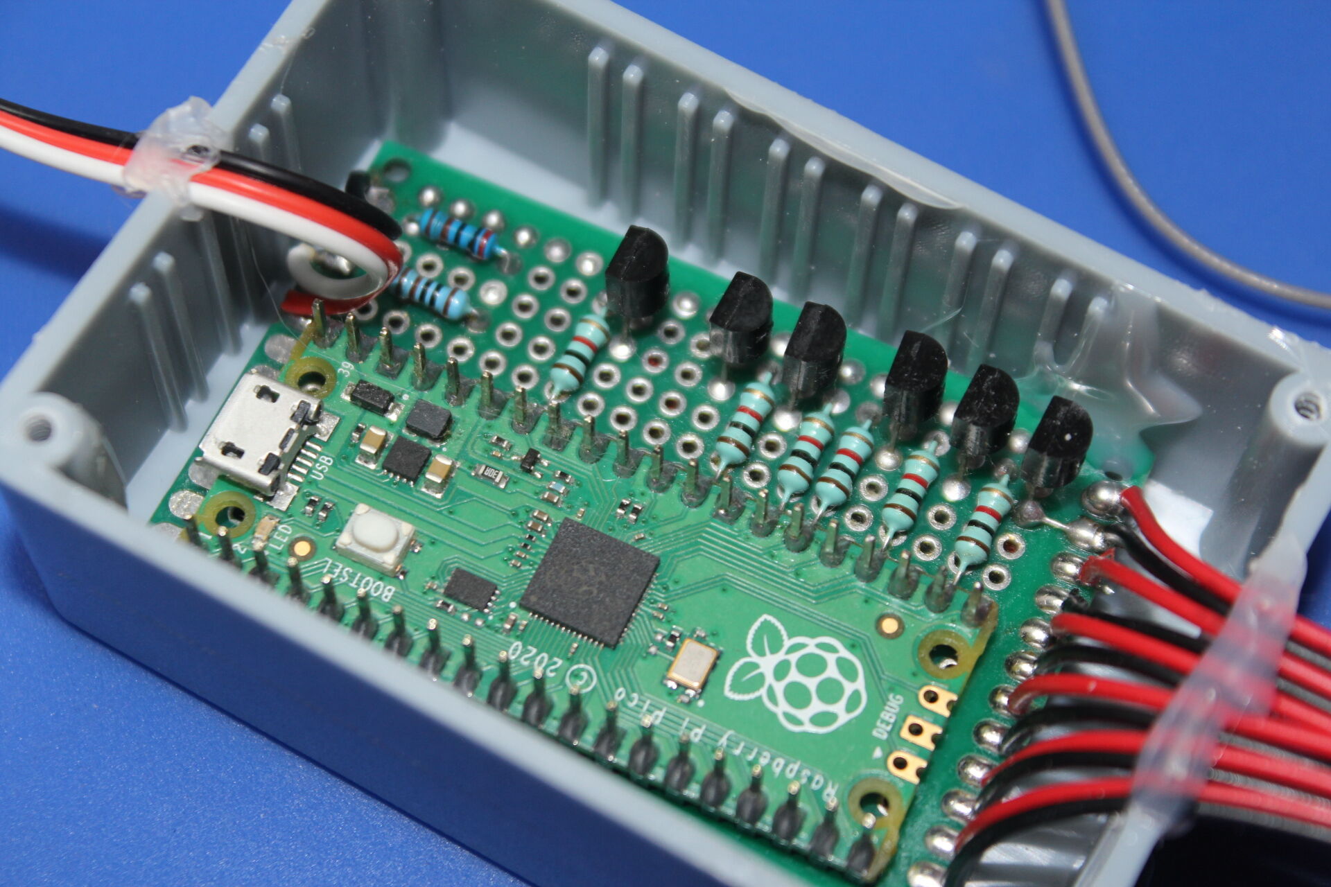
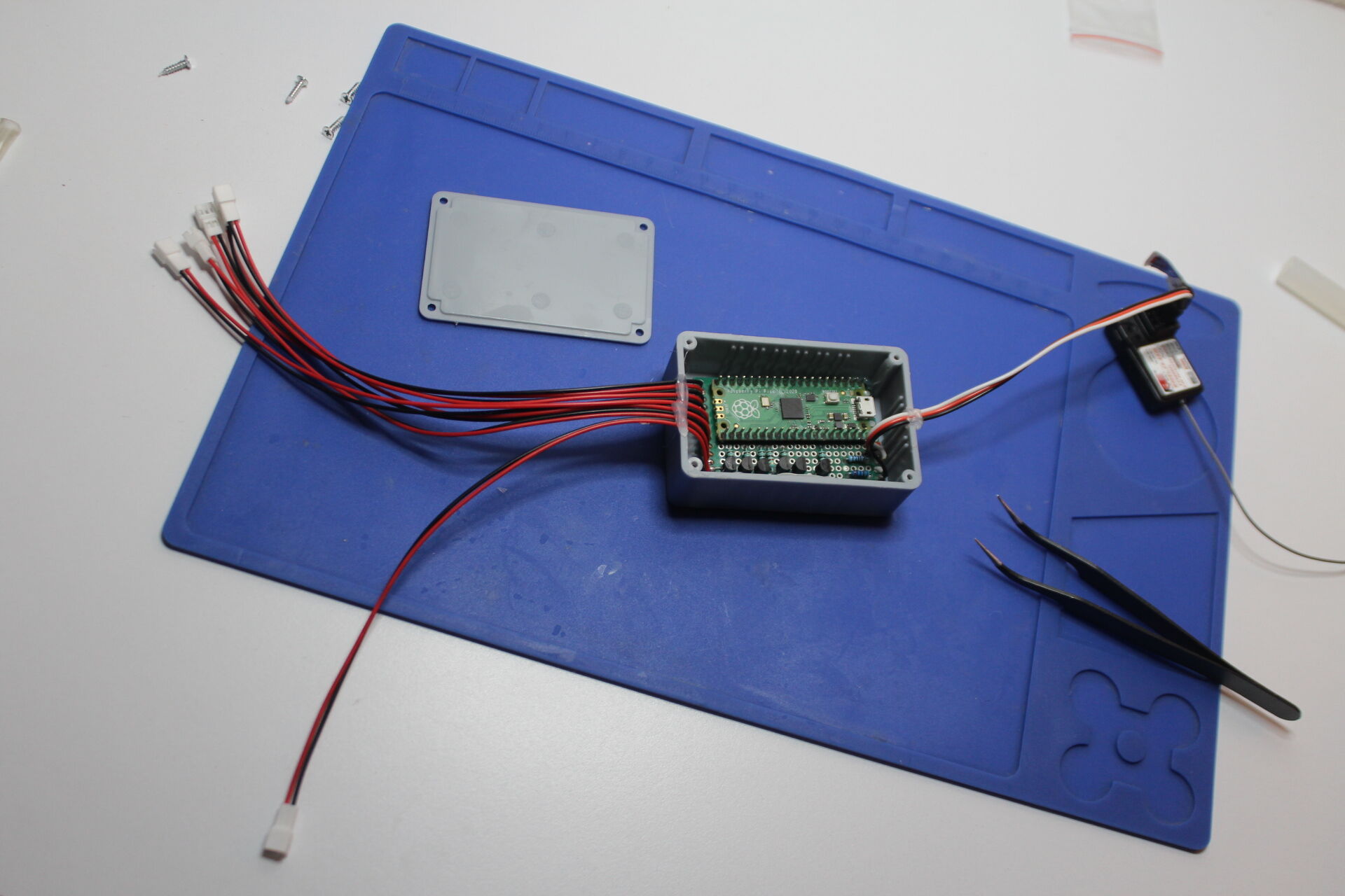
We productionize the controller by soldering all the components on an perfboard and encasing it in a plastic box as shown in the following two pictures. The leds and the resistors that limit their current remain attached to the body so that we can reuse the controller with different led types and sizes.
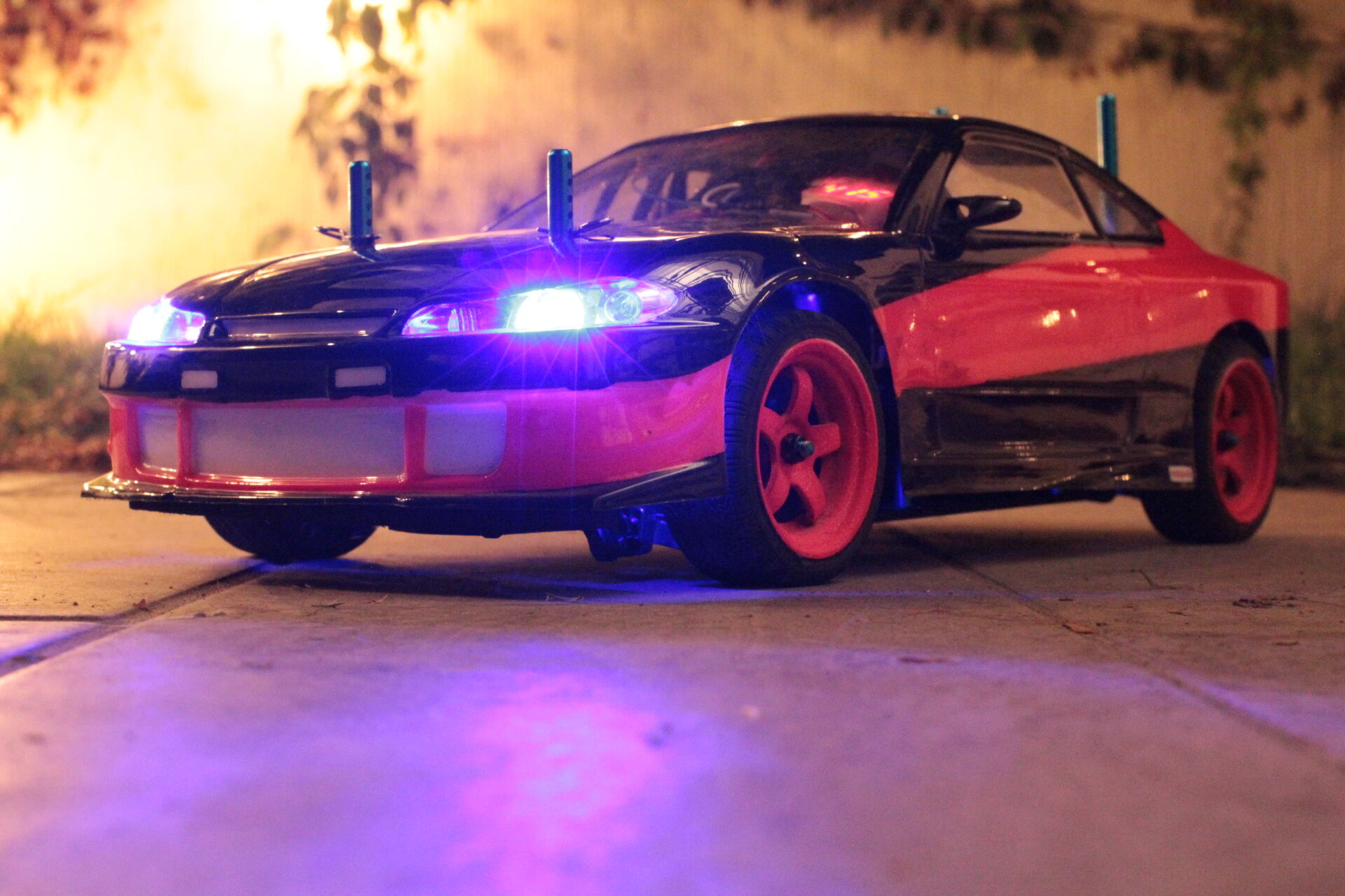
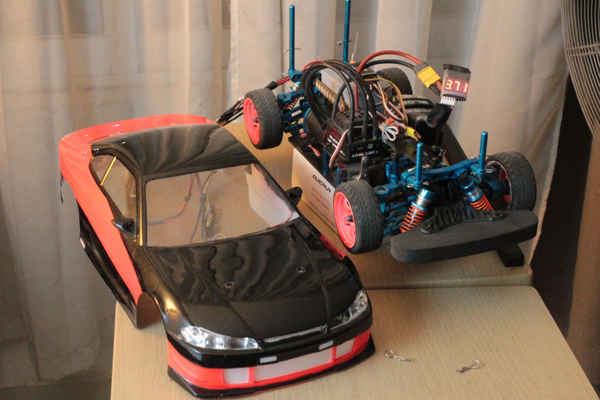
Finally, we install the controller in our RC car and connect the wire loom to the body shell.
Conclusion
The Raspberry Pico offers great potential for artistic expression and room for developing future features.
In the case of artistic freedom, our sample implementation is able to accept different body shells with drastically different sets of lights.
In the case of future features, we could, for example, run different programs for different cars. The selection of one program or another could be made with a physical switch or with an additional channel.