How to add sound to a broken Skyzone 04o Pro
A known shortcoming of the Skyzone 04o Pro FPV goggles is lack of sound in some production batches. In this article we explain how to overcome this issue by adding an electronic component that is missing from the factory. The goggles that we will use to illustrate the fix were purchased at the beginning of 2026, see Figure 1. Although the goggles are otherwise functional, the lack of sound is unexpected and not disclosed when you buy the goggles.
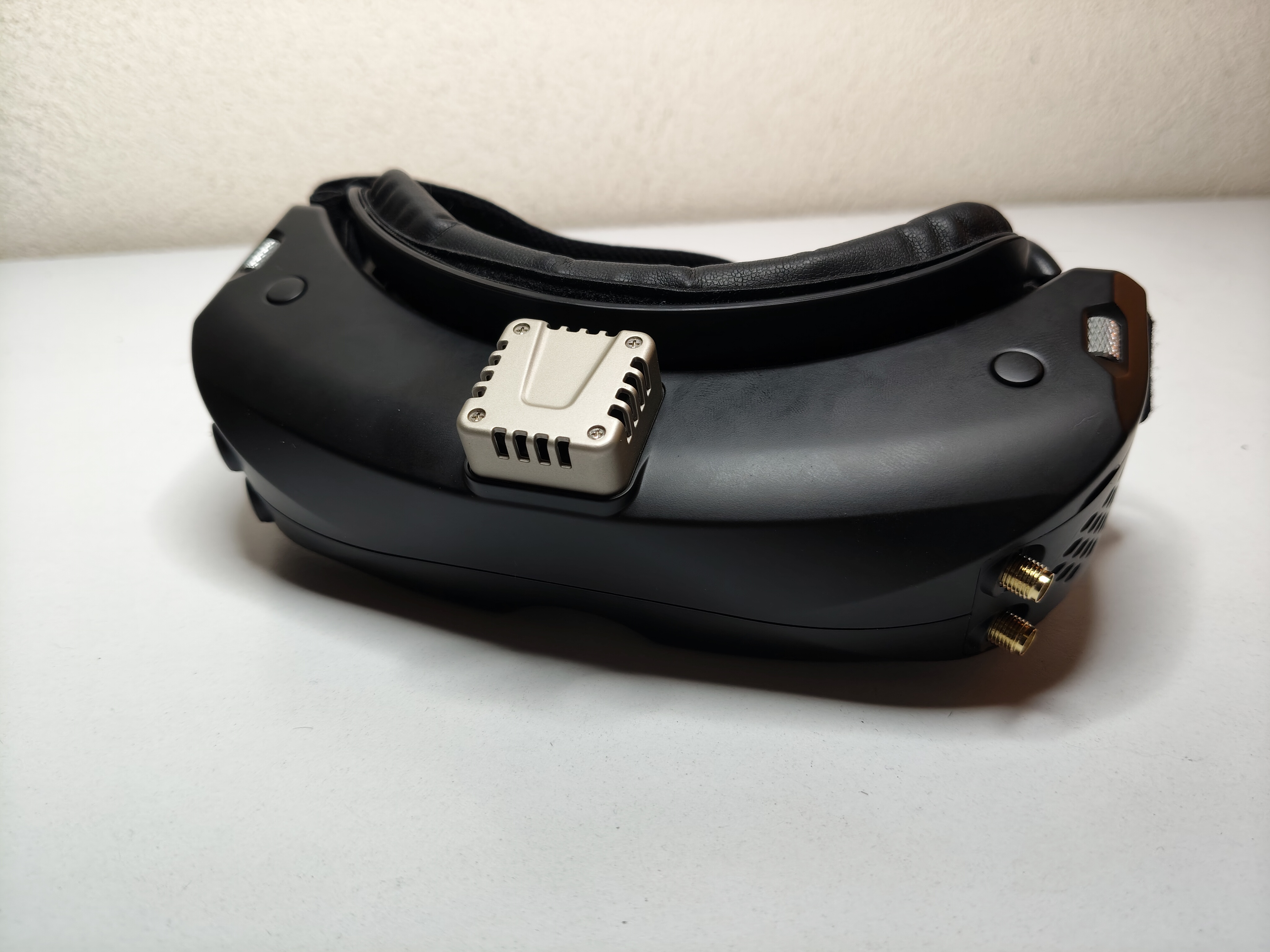 Figure 1. Skyzone 04o Pro FPV goggles bought at the beginning of 2026.
DISCLAIMER
DISCLAIMER: The contents of this blog post are published with all faults and without any guarantee of any kind and we assume no liability for what you do with anything explained here. Do not try to reproduce anything explained here without adult supervison. If you do try to reproduce anything explained here, do it at your own risk. Working with electronics will expose you to health hazards and potential loss of property, including but not limited to toxic fumes, lead poisoning, and fire hazards. Always wear eye protection and work in a well ventilated area.
Related work
- Here is a Youtube video that shows how to fix the issue using the same approach we use. However, the video does not explain that the component used, a ceramic filter, can be confused with another similar component, a ceramic trap.
- Here is a Reddit thread that denounces the issue and links to the previous video.
- Here is a Youtube video denouncing a different kind of issue that adds on top of this one. These goggles and others suffer from a latency comparable to that of a digital system and thus removes one crucial advantage of analog systems for very experienced pilots.
- Here is a Reddit thread where the previous latency issue is supossedly not going to be addressed by Skyzone.
Root cause
The lack of sound originates from the video receiver module. In our case, the receiver module is a Skyzone Steadyview v3.3, see Figure 2.
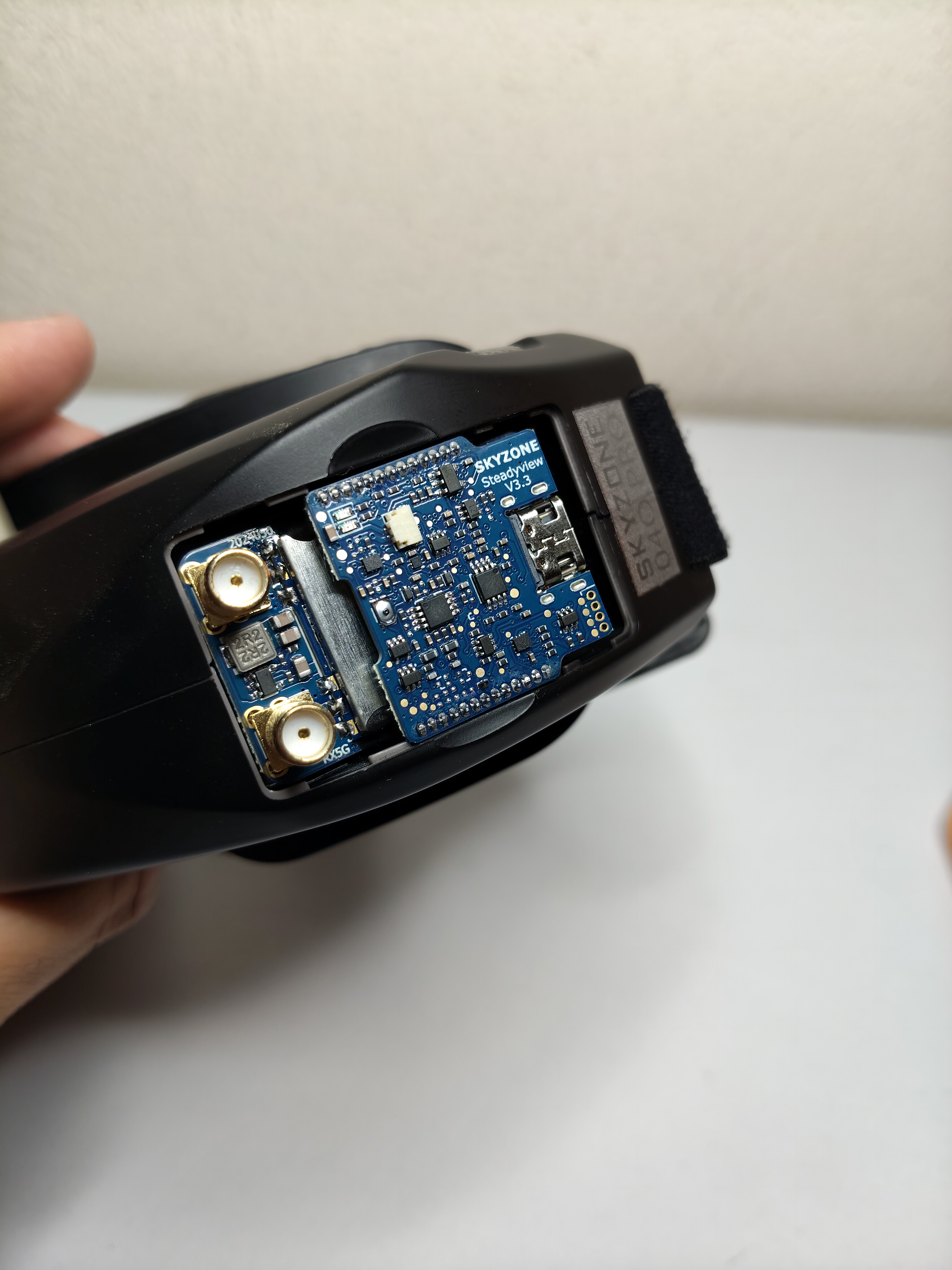 Figure 2. Skyzone Steadyview v3.3 video receiver module installed in the goggles.
The root cause of the lack of sound is that the video receiver module is missing two 6.5Mhz ceramic filters like the one depicted in Figure 3. The ceramic filter depicted in Figure 3 was purchased from AliExpres with our own money so this is not a paid promotion.
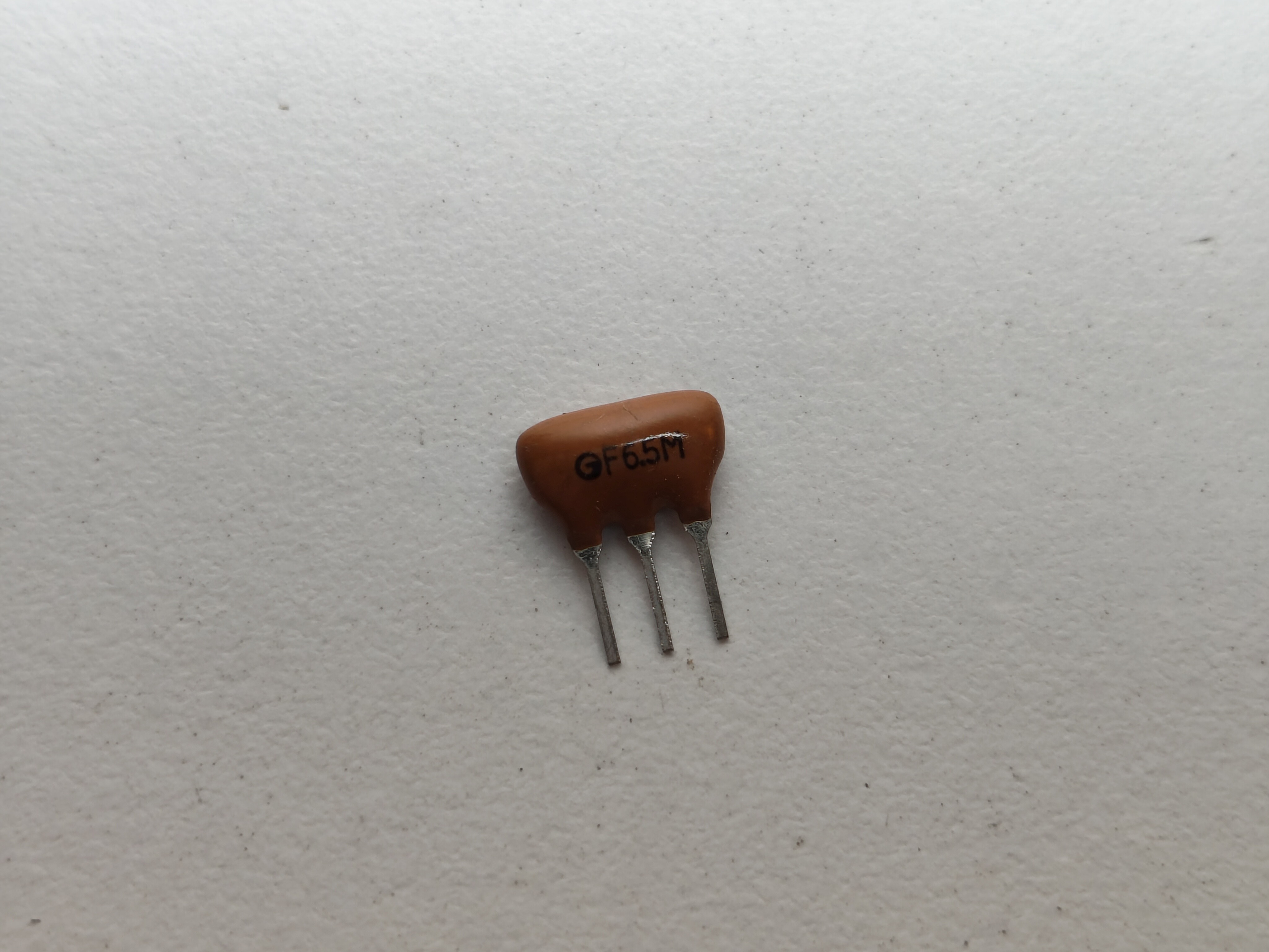 Figure 3. In-Line Ceramic Filter L6.5C L6.5MSFSH6.5MCB 6.5MHz.
The purpose of the ceramic filter is to allow the parts of the signal around 6.5Mhz to pass and reject the rest of the signal. Here is a spec sheet for another filter of the same characteristics. You should not confuse this filter with another similar component called a trap. The purpose of a trap is to reject the parts of the signal around a given frequency, for example 6.5Mhz, and allow the rest of the signal to pass. Here is an AI conversation that explains the difference.
Installation procedure
The procedure to install the two missing ceramic filters is the following.
Step 1. Remove the video receiver module from the googles.
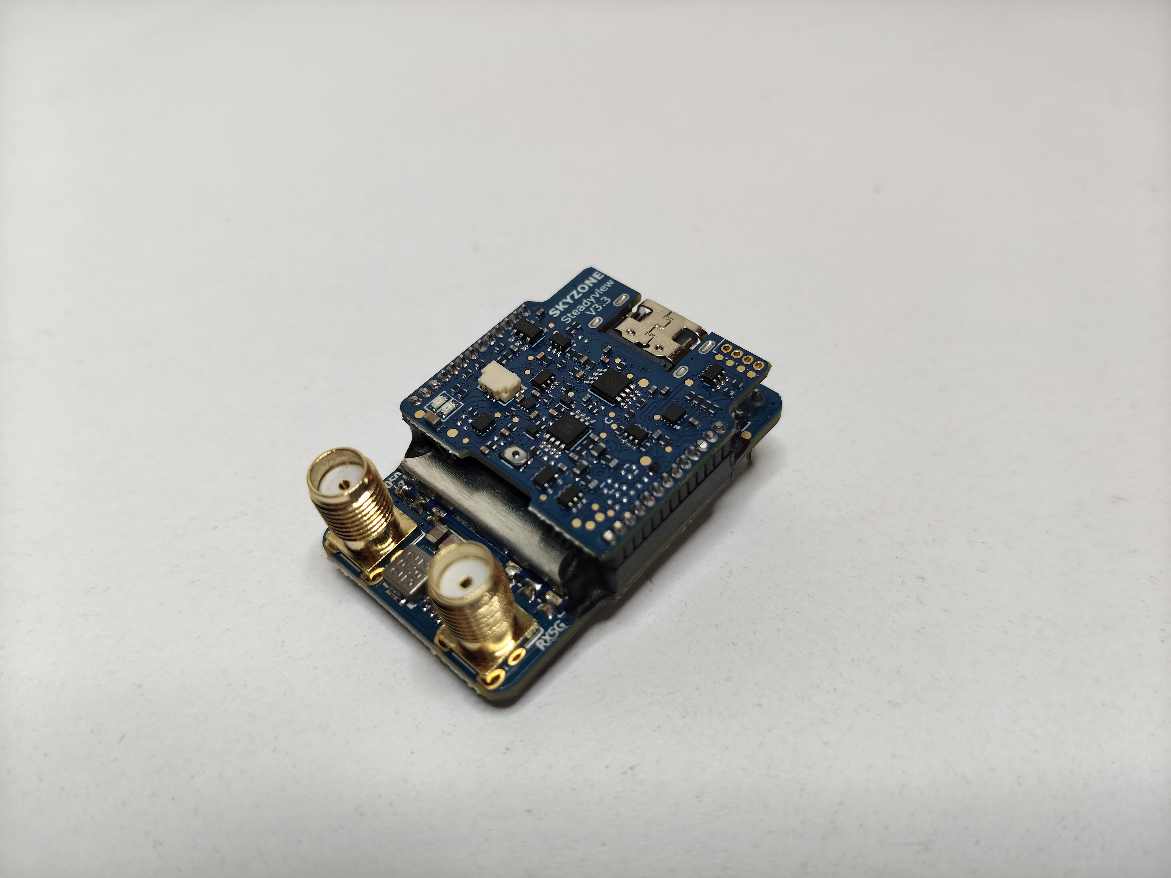 Figure 4. Skyzone Steadyview v3.3 video receiver module.
Step 2. Remove the metal plate on the back of the receiver module.
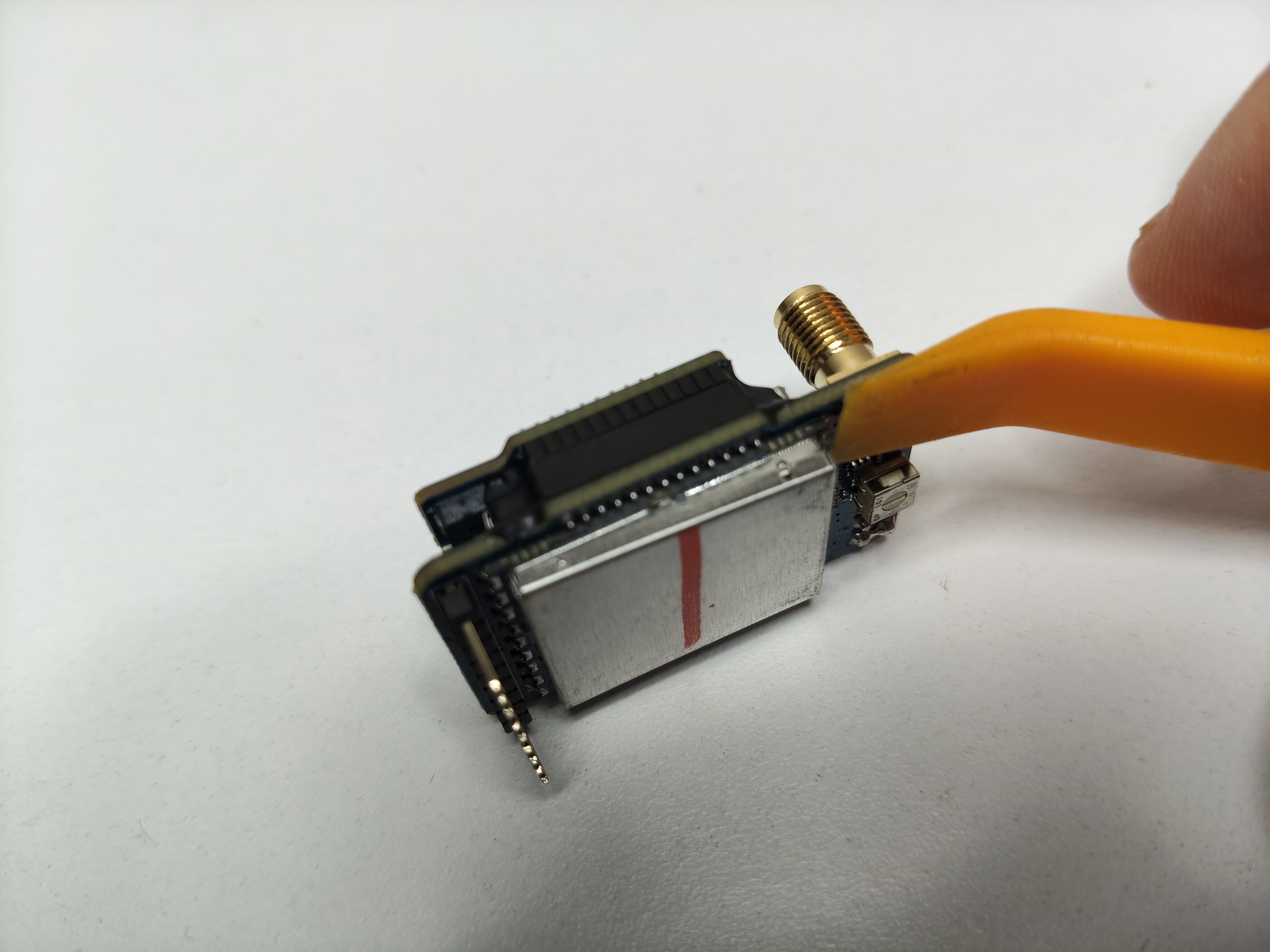 Figure 5. Carefully pry open the metal plate on the back of the video receiver module.
Step 3. Locate the dedicated slot for the ceramic filter.
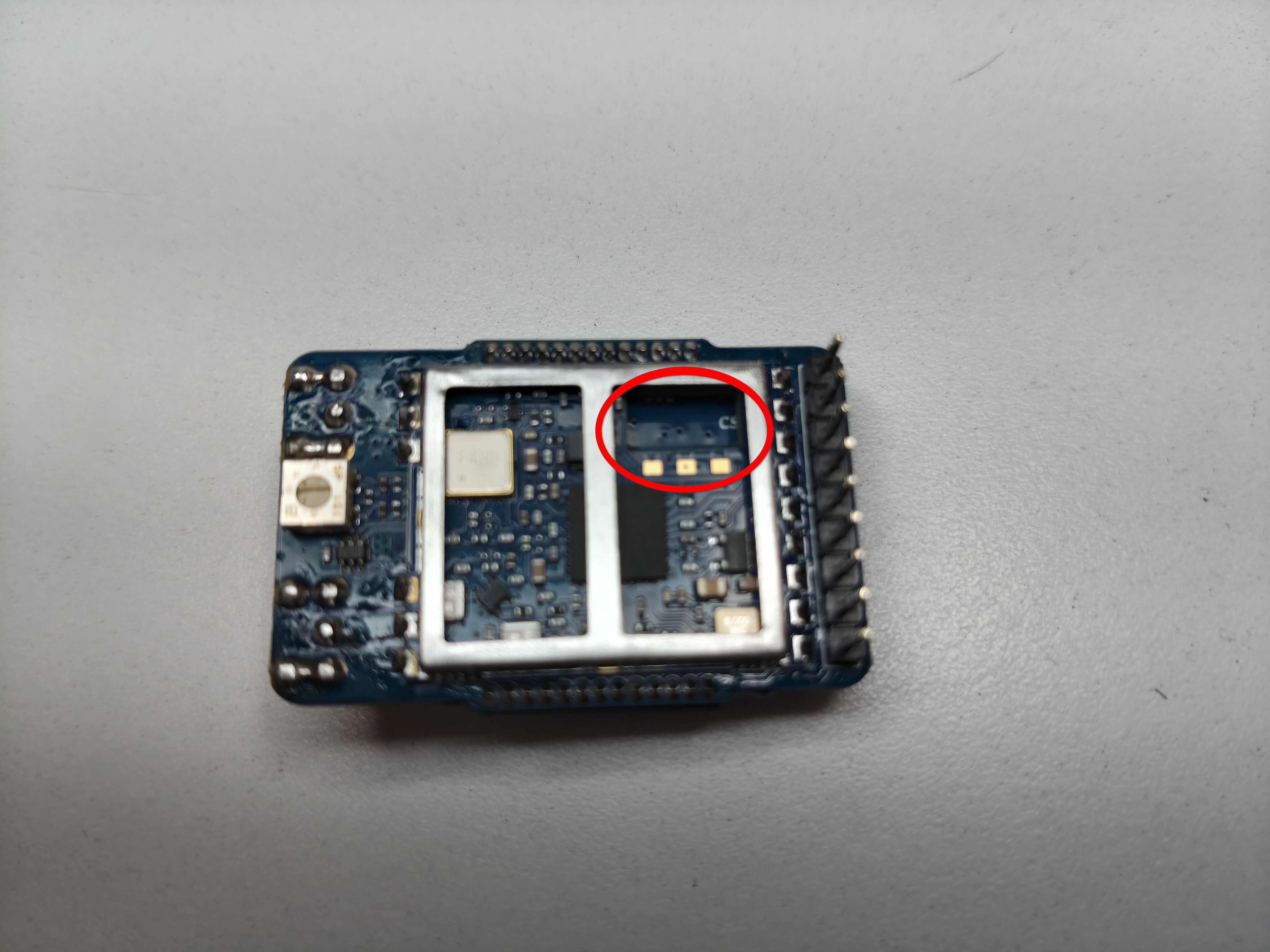 Figure 6. Location of slot for the ceramic filter on the back of the video receiver module.
Step 4. Select a ceramic filter that will sit as flush as possible with the frame that holds the metal frame. Ceramic filters do not have all the same exact shape but they have slight variations. Some are bigger than others in one dimension or another. So you have to carefully choose a filter that sits as flush as possible. This is crucial so that when you put back the video receiver module together and then install it in the goggles, you can actually close the plastic lid that protects the module.
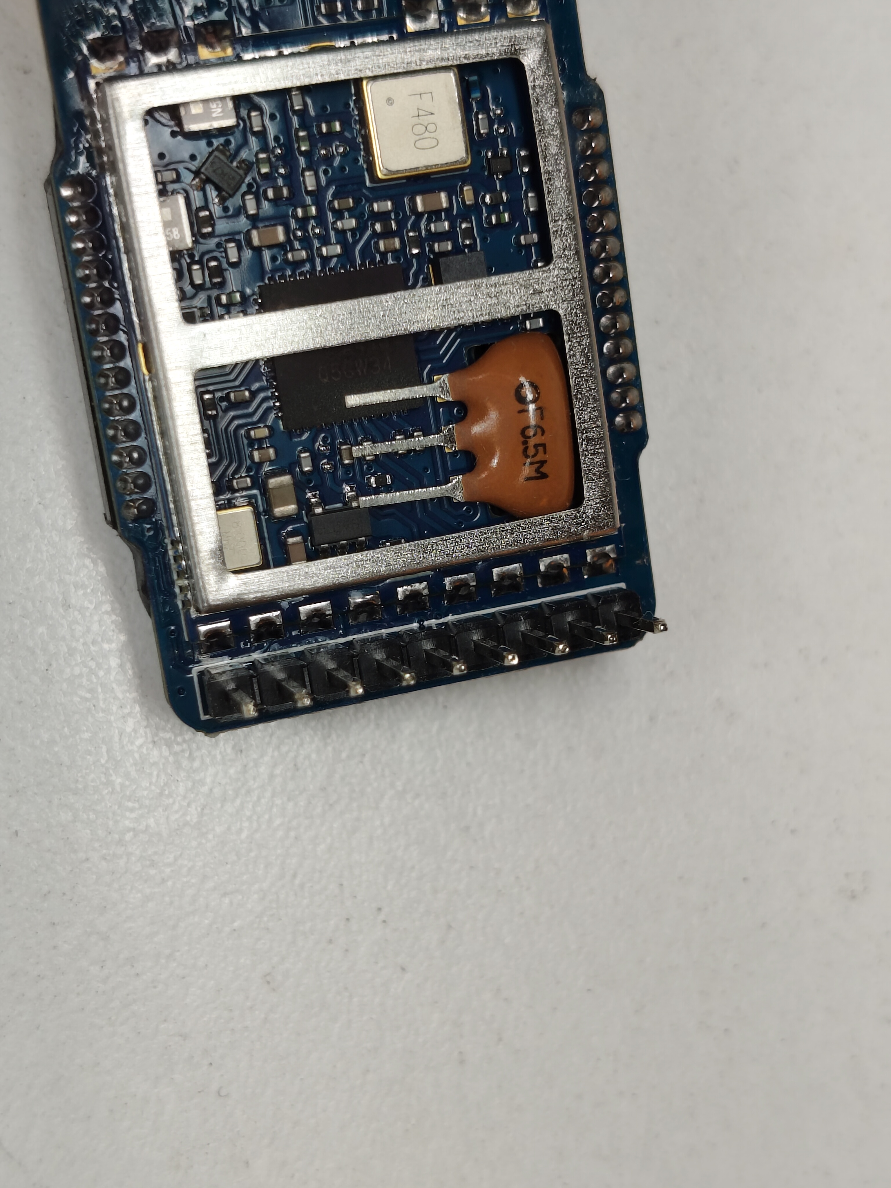 Figure 7. Try out different ceramic filters from a batch so that you find the best fit.
If necessary, you can carefully trim the frame that supports the metal plate to achieve a better fit, see Figure 8.
Step 5. Solder the ceramic filter with the letters facing to you. The ceramic filter we used is polarized and we found that orienting it with the letters facing “up” worked for us. This also seems to be the way the video module comes out of the factory when ceramic filters are included, see this Reddit comment. You might need to trim the legs of the filter in addition to trimming the metal frame near the slot for the filter, see Figure 8.
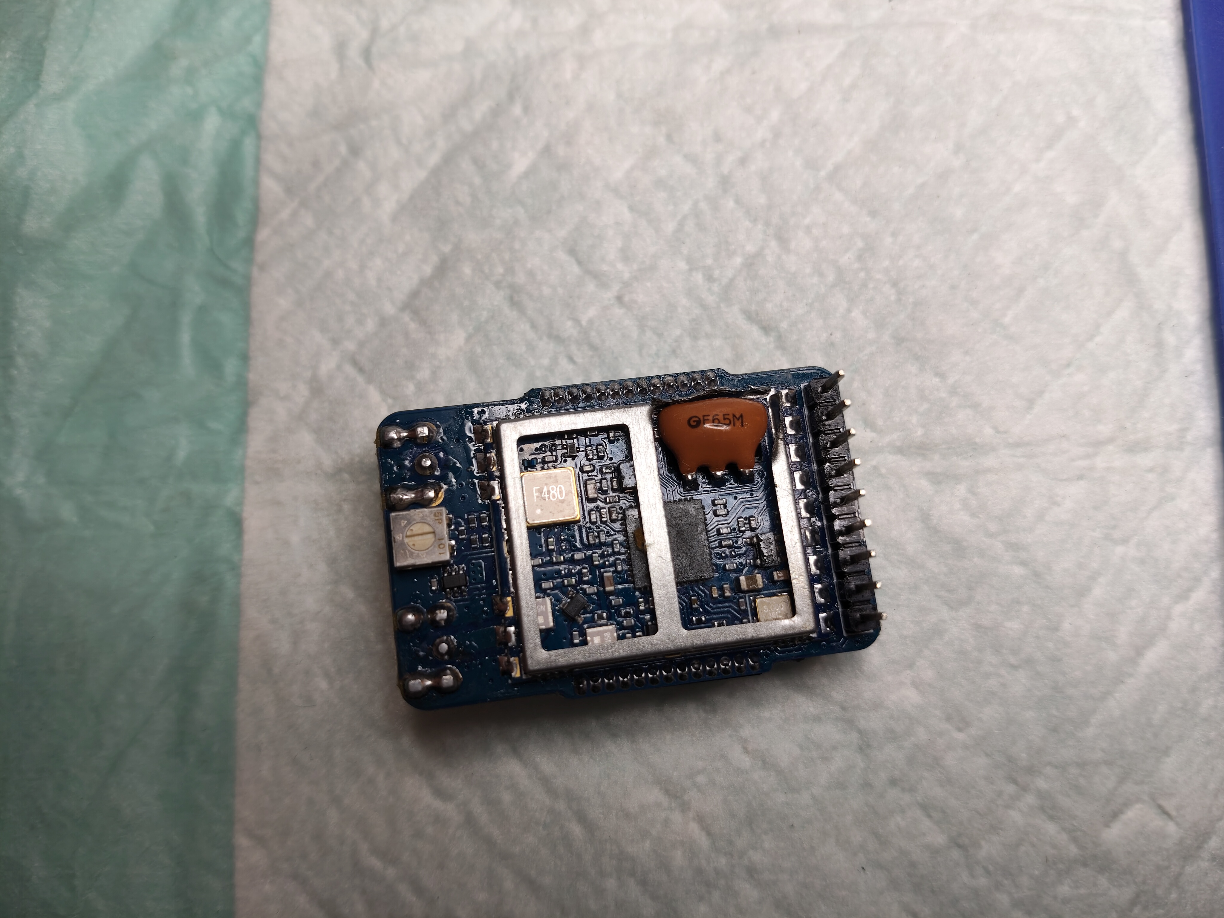 Figure 8. First ceramic filter soldered in its slot and in the right orientation.
Step 6. Uncover a second metal plate that is sandwiched between the two boards that make the receiver module. You will find another metal plate and another slot for the second ceramic filter sandwiched in between the two boards that make the video module. The two boards are bound together with an adhesive that can be removed very carefully so that no components are damaged, see Figure 9.
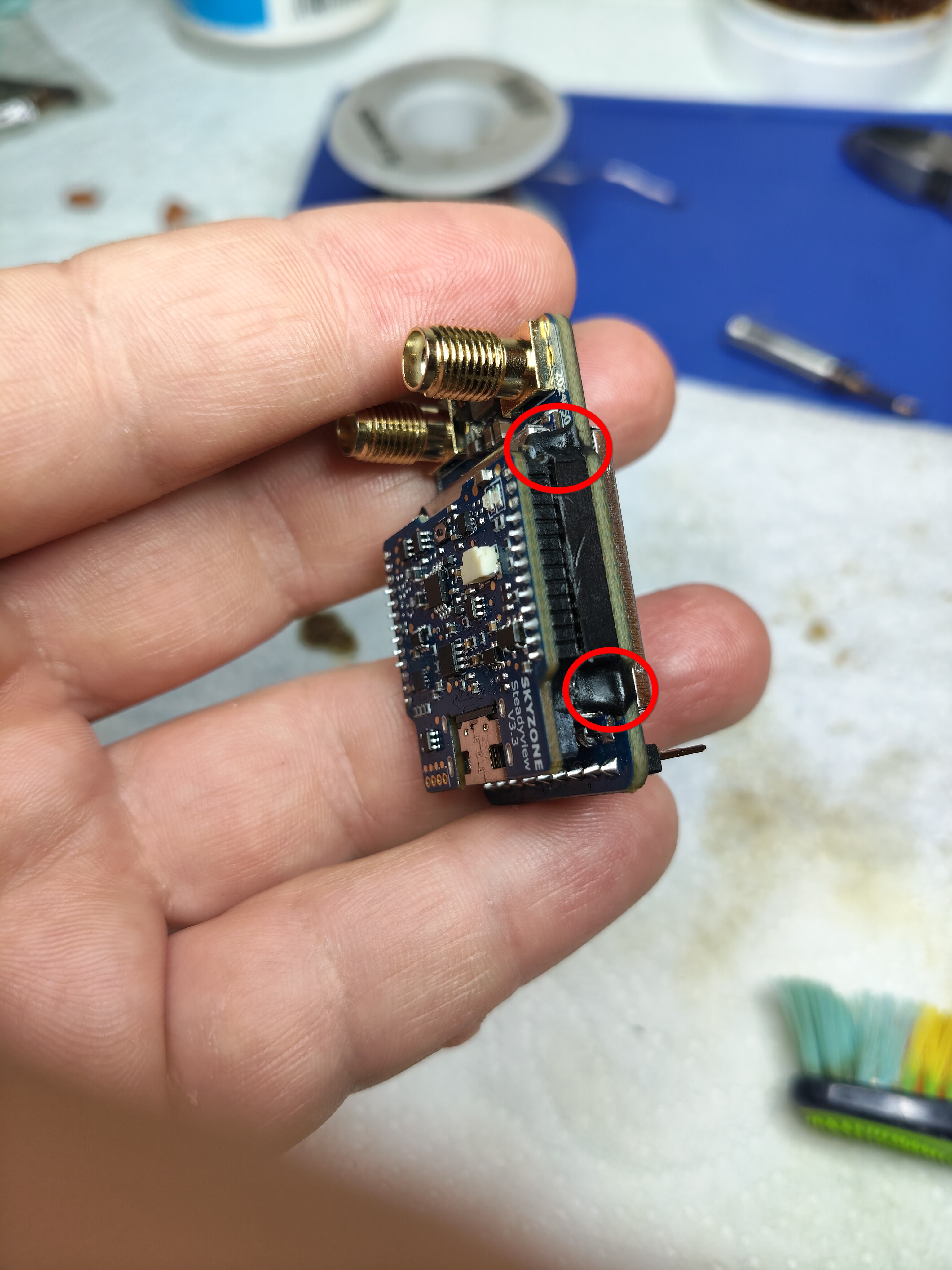 Figure 9. Location of the adhesive that holds together the two boards that make the video receiver module.
Step 7. Solder the second ceramic filter in the dedicated slot. Remove the metal plate that you just uncovered. The second ceramic filter should be placed in a slot that is identical to the slot of the first filter. Again, make sure that you choose a filter that will sit flush and trim the metal frame as necessary, see Figure 10. It is even more critical that this second filter sits flush so that you can close the metal plate and sandwich the two boards together.
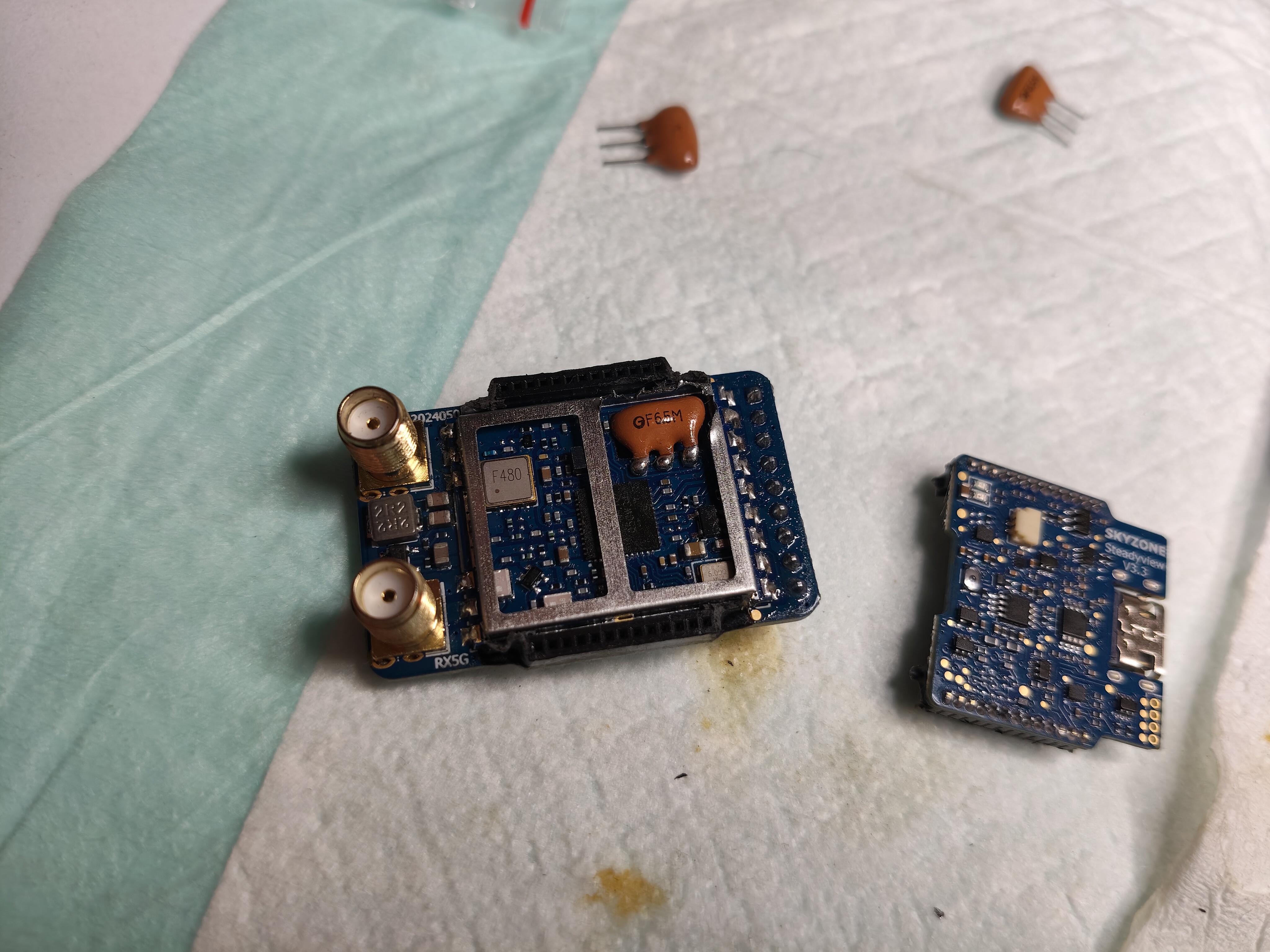 Figure 10. Second ceramic filter soldered in its slot and in the right orientation.
Step 8. Put back together the video receiver module and make sure you can close the plastic lid.
Result
After installing both ceramic filters, audio becomes available to any plugged headphones as well as to the DVR. See (and hear) the following recording.